심냉 공기분리공정의 공기압축공정에서 전력비 절감을 위한 액화천연가스 냉열 활용에 대한 연구
2020 The Korean Hydrogen and New Energy Society. All rights reserved.
Abstract
In this work, a study for the reduction of the electric power consumption has been estimated in main air compressors in the air separation unit through cryogenic distillation columns with PRO/II with PROVISION V10.2 at AVEVA company. Both required LNG mass flow rate and cold heat contained in 1 ton of LNG were also predicted using Peng-Robinson equation of state with Twu’s new alpha function. Through this work, we concluded that 32.33―48.69% of electric power could be saved by using LNG cold heat.
Keywords:
Air separation unit, Compressor, Cryogenic distillation column, LNG, Cold heat키워드:
공기분리공정, 압축기, 심냉 증류탑, 액화천연가스, 냉열1. 서 론
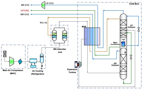
심냉 증류를 통한 공기분리공정의 개요는 Fig. 1과 같다1). Fig. 1에 의하면 공기 중에 포함되어 있는 이산화탄소 및 탄화수소 등과 같은 불순물을 제거한 후에 main air compressor (MAC)에서 약 5.5 bar까지 중간에 냉각기를 가지는 3단 압축에 의해서 가압된다. 가압된 공기는 냉동 공정을 거친 후에 온도가 더욱 내려간다. 그 후에는 분자체를 거친 후에 공기 중의 수분을 0.1 ppm 이하까지 제거한다. 분자체를 거친 후에 공기는 main heat exchanger에 의해서 열교환된 후에 심냉 증류공정으로 주입된다. 심냉 증류탑은 상부의 저압 증류탑과 하부의 고압 증류탑으로 구성되어 있다. 경우에 따라서 아르곤을 분리하는 별도의 증류탑을 가동하기도 한다2).
본 연구에서는 중간에 냉각기를 가지는 3단 공기 압축공정에서 첫 번째 압축기 전단과 각각의 중간 냉각기 후단에 액화천연가스(LNG)를 이용하여 공기를 더욱 냉각시킴으로써 MAC 공정에서 소요되는 총 전력비용을 절감하는 연구를 수행하였다.
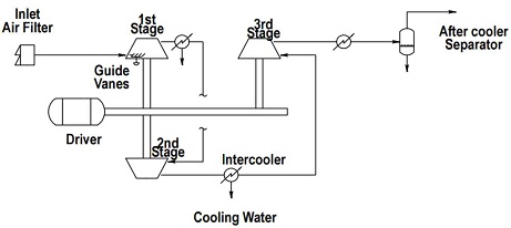
Fig. 2에는 3단 MAC 공정에 대한 개요도를 나타내었다. Fig. 2에 의하면 대기는 필터를 통해서 먼지가 제거된 상태에서 첫 번째 압축기 전단으로 주입된다. MAC에서는 일반적으로 전기 모터를 사용하며, 심냉 증류를 통한 대부분의 공기분리공정에서 소모되는 전력은 MAC에서 소모되고 있다3).
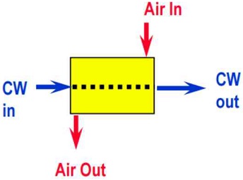
압축기 사이에서는 냉각수만을 사용하여 공기의 온도를 35-40℃ 정도로 낮추는 경우가 있다. 이는 중소형 공기분리공정에 적용하는 공랭식 방식이며, 이는 Fig. 3에 나타내었다4). 이 경우에는 후단 분자체 타워의 용량이 커질 수 있는 단점이 있다. 한편 Fig. 4에는 냉각수와 냉동기를 동시에 순차적으로 사용한 경우에 대한 개요도를 나타내었다. 이 경우에는 중대형 공기분리공정에 적용하는 방식이며, 냉동기를 사용하여 공기의 온도를 약 5-20℃ 이하로 냉각한다. 이 경우에는 후단의 분자체의 타워의 용량을 작게 할 수 있다는 장점이 있다5).
본 연구에서는 Fig. 4에서 증기 재압축 냉동기를 설치하는 대신에 LNG의 냉열을 활용함으로써 절감되는 3단 공기 압축기의 동력비용을 추산하였으며, 이때 소요되는 LNG의 필요 유량 및 LNG 1톤에 함유되어 있는 냉열을 추산하였다.
LNG의 경우에는 한국가스공사(주)6)에서 수입하고 있는 4가지 종류에 대해서 모두 적용하였으며, 3단 압축기의 소요 동력을 절감하기 위해서 사용하는 증기 재압축 냉동기에서 사용되는 냉매는 순수한 노말 부탄으로 가정하였다.
2. 전산모사
전제 공정에 대한 전산모사는 Peng-Robinson 상태방정식7)을 활용하였으며, 순수성분의 온도에 따른 증기압을 좀 더 잘 추산하기 위한 Twu의 새로운 alpha function8)을 적용하였다.
2.1 기존 공기압축공정에 대한 전산모사
Table 1에는 MAC로 주입되는 공기의 조건과 각 압축기 후단에서의 온도 및 압력 조건을 나타내었다.
Fig. 5에는 Fig. 2에 나타낸 MAC 공정에 대한 PRO/II를 이용한 flow sheet를 나타내었다.
Table 2에는 Fig. 5의 PRO/II를 이용한 전산모사 결과를 요약 및 정리하였다. Table 2에 의하면 첫 번째와 두 번째 및 세 번째 압축기의 소요 동력을 각각 4,443 kW와 3,792 kW 및 3,361 kW이며, 총 소요 동력은 11,596 kW임을 알 수 있다. 1 kWh 당 산업용 전기료를 100원으로 가정하고, 1년 365일, 하루 24시간 압축기를 가동한다고 가정하면 연간 소요되는 전력비는 식 (1)과 같다. 식 (1)의 계산결과에 의하면 연간 전력비는 약 101억 5천 8백만 원가량임을 알 수 있다.
| (1) |
2.2 냉동기를 추가한 공기압축공정에 대한 전산모사
Fig. 6에는 기존의 냉각수를 사용한 inter-cooler 이외에 첫 번째 압축기 전단과 각 inter-cooler 후단에서 냉각수를 이용한 냉각기 후단에 부탄 냉매를 이용한 냉각기를 추가하였다.

PRO/II flow sheet drawing for MAC with pre-cooler and inter-coolers using both cooling water and refrigerant
Table 3에는 Fig. 6의 PRO/II를 이용한 전산모사 결과를 요약 및 정리하였다. Table 3에 의하면 부탄 냉매를 사용해서 pre-cooler와 각각의 inter-cooler를 사용한 결과 첫 번째와 두 번째 및 세 번째 압축기의 소요 동력을 각각 3,005 kW와 2,934 kW 및 3,107 kW로 줄었으며, 총 소요 동력은 9,046 kW로 11,596 kW에 비해서 약 22%가량 줄어들었음을 알 수 있다.
2.3 부탄 냉동기의 전산모사
부탄 냉동기에서 냉매 증발기의 heat duty는 Table 3에 의하면 4.3747×10⁶ kcal/h인 것을 알 수 있다. Fig. 7에는 부탄을 냉매로 사용한 증기 재압축 냉동 사이클에 대한 PRO/II flow sheet를 나타내었다.

PRO/II flow sheet drawing for vapor-recompression refrigeration cycle using normal butane as a refrigerant
Table 4에는 Fig. 7의 전산모사 결과를 요약하여 정리하였다. 냉매 압축기의 소요 동력은 888 kW인 것을 알 수 있다. 이로부터 Table 3에서의 총 소요 동력은 9,046 kW로 줄어든 반면에 냉동기 소요 동력으로 888 kW가 새로이 필요하게 되었으므로 총 필요한 소요 동력은 9,934 kW인 것을 알 수 있다. 냉각수만을 이용하는 경우에 필요한 소요 동력이 11,596 kW이므로 여전히 14.3%가량의 전력이 절감되는 것을 알 수 있다. 식 (2)에는 절감되는 전력인 1,662 kW만큼의 연간 전력비용을 나타내었다. 식 (2)에 의하면 절감되는 동력비는 연간 14억 5천 5백만 원가량임을 알 수 있다.
| (2) |
2.4 LNG 냉열 활용 공기압축공정에 대한 전산모사
증기 재압축 냉동 사이클을 이용하는 대신에 -163℃로 공급되는 LNG의 냉열을 활용하면 공기의 온도를 더욱 냉각시킬 수 있으므로 압축기의 소요 동력을 더 많이 줄일 수 있다. 본 연구에서 사용한 LNG의 조성은 Table 5에 나타내었다. Table 5에 의하면 LNG의 조성은 에탄 함량이 많고 적음에 따라서 rich case와 lean case로 나뉘며, 질소가 최대로 함유된 Max. N2 case 및 전형적인 조성을 갖는 경우의 4가지로 나누어진다. 4가지 경우 모두 LNG의 공급 온도는 –163oC를 가정하였으며, 공급압력은 8.5 bar로 지정하였다.
각각의 LNG에 대해서 잠열만을 이용한다고 했을 때, LNG 증발기 후단의 온도를 Table 6에 나타내었다. 그리고 공기와 LNG와의 온도 차이는 3℃로 가정하였다. Table 7에는 각각의 경우에 대한 pre-cooler와 inter-cooler에서 heat duty와 각각의 압축기에 대한 소요 동력을 나타내었다.
3. 결과 및 토론
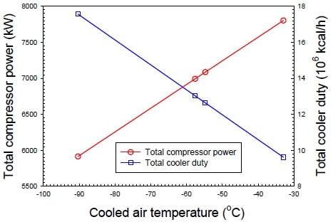
Fig. 8에는 각각의 LNG의 조성별 냉각 가능한 공기의 출구 온도별 압축기의 총 소요 동력과 pre-cooler 및 inter-cooler의 heat duty의 총합을 그래프로 도시하였다. Fig. 7에 의하면 3기의 압축기의 소요 동력의 총 합은 공기의 온도를 낮게 냉각할수록 선형적으로 감소하는 것을 알 수 있으며, 냉각기의 heat duty의 합은 공기의 온도를 낮게 할수록 증가하는 것을 알 수 있다. 이는 LNG로 공기의 온도를 낮게 유지할수록 냉각기에서 회수 가능한 냉열은 증가하며 또한 그에 비례하여 압축기의 총 소요 동력은 비례하여 감소한다는 것을 의미한다.
Table 8에는 각각의 LNG 조성별로 필요한 유량과 연간 소요되는 전력비용 및 LNG 톤에 함유되어 있는 냉열 가격 등을 산출하여 정리하였다.
4. 결 론
심냉 공기분리공정의 공기압축공정에서 전력비 절감을 위해서 LNG의 냉열을 활용한 결과 다음과 같은 결론을 얻을 수 있었다.
1) 3단 압축 공정에서 inter-cooler 후단의 온도를 냉각수로 40℃까지 낮춘 것에 비해서 노말 부탄을 냉매로 사용하여 5℃까지 pre-cooler와 inter-cooler를 사용하여 공기의 온도를 낮춘 결과 연간 총 전력비용을 22% 절감할 수 있었다.
2) 한국가스공사에서 제공받는 4가지 종류의 LNG의 냉열을 활용하여 공기 압축기 전단과 사이의 온도를 낮춘 결과 냉각수만을 이용한 공기압축공정에 비해서 연간 전력비용을 32.33%에서 많게는 48.69%까지 절감할 수 있었다.
3) LNG를 이용하여 냉각할 수 있는 공기의 온도의 함수로 압축기 소요 동력을 도시해 본 결과 정확하게 정비례하는 것을 알 수 있었으며, pre-cooler와 inter-cooler의 heat duty의 합은 정확하게 반비례하는 관계에 있는 것을 알 수 있었다.
References
- H. C. Choi, H. M. Moon, and J. H. Cho, “A study on the optimal process design of cryogenic air separation unit for oxy-fuel combustion”, Korean Chem. Eng. Res., Vol. 56, No. 5, 2018, pp. 647-654.
- H. C. Choi, H. M. Moon, and J. H. Cho, “Exergy analysis of cryogenic air separation unit for oxy-fuel combustion”, KIGAS, Vol. 23, No. 1, 2019, pp. 27-35.
- P. S. Yong, H. M. Moon, and S. C. Yi, “Exergy analysis of cryogenic air separation process for generating nitrogen”, J. of Industrial and Engineering Chemistry, Vol. 8, No. 6, 2002, pp. 499-505. Retrieved from https://www.cheric.org/research/tech/periodicals/view.php?seq=384469, .
-
A. Ebrahimi and M. Ziabasharhagh, “Optimal design and integration of a cryogenic air separation unit (ASU) with liquefied natural gas (LNG) as heat sink, thermodynamic and economic analyses”, Energy, Vol. 126, 2017, pp. 868-885.
[https://doi.org/10.1016/j.energy.2017.02.145]

-
M. Aneke and M. Wang, “Potential for improving the energy efficiency of cryogenic air separation unit (ASU) using binary heat recovery cycles”, Applied Thermal Energy, Vol. 81, 2015, pp. 223-231.
[https://doi.org/10.1016/j.applthermaleng.2015.02.034]

- Y. W. Kim, J. S. Lee, J. J. Lee. D. S. Kim, and J. H. Cho, “Optimization study on the open-loop rankine cycle for cold heat power generation using liquefied natural gas”, Trans. of Korean Hydrogen and New Energy Sociecy, Vol. 28, No. 3, 2017, pp. 295-299.
-
D. Y. Peng and D. B. Robinson, “A new two-constant equation of state”, Ind. Eng. Chem. Fundam., Vol. 15, No. 1, 1976, pp. 59-64.
[https://doi.org/10.1021/i160057a011]

-
C. H. Twu, D. B. Bluck, J. R. Cunningham, and J. E. Coon, “A cubic equation of state with a new alpha function and a new mixing rule”, Fluid Phase Equilibria, Vol. 69, 1991, pp. 33-50.
[https://doi.org/10.1016/0378-3812(91)90024-2]


