한국수소및신에너지학회 학술지영문홈페이지
[ Article ]
Journal of Hydrogen and New Energy - Vol. 35, No. 5, pp.601-616
ISSN: 1738-7264 (Print) 2288-7407 (Online)
Print publication date 31 Oct 2024
Received 04 Oct 2024 Revised 23 Oct 2024 Accepted 25 Oct 2024
DOI: https://doi.org/10.7316/JHNE.2024.35.5.601

기체 및 액화수소 자동차충전소 위험성 평가를 통한 안전거리 적정성 연구

서원석 ; 신헌용
서울과학기술대학교 에너지화학공학과
A Study on the Adequacy of Safety Distances through Quantitative and Qualitative Risk Assessment of Gas and Liquid Hydrogen Vehicle Charging Stations
WON SEOK SEO ; HUN YONG SHIN
Department of Energy and Chemical Engineering, Seoul National University of Science&Technology, 232 Gongneung-ro, Nowon-gu, Seoul 01811, Korea

Correspondence to: hyshin@seoultech.ac.kr

2024 The Korean Hydrogen and New Energy Society. All rights reserved.

Abstract

In order to increase the public acceptance of hydrogen in the process of expanding the supply of gaseous hydrogen and liquid hydrogen vehicle charging stations in accordance with the government's revitalization of the hydrogen economy policy, the safety of hydrogen vehicle charging stations has been strengthened through the introduction of a risk assessment system, unlike the existing liquefied petroleum gas or high-pressure gas charging stations. In this paper, a risk assessment was conducted for the newly introduced hydrogen vehicle charging station, and a comparative analysis was conducted between the results and the required legal safety distance. To this end, the node classification for the qualitative evaluation of hydrogen refueling stations was classified in the same way as the safety distance facility classification of the law, and the fire explosion caused by hydrogen leakage was separately classified among the scenarios according to the risk review results to conduct a quantitative risk assessment. As a result of quantitative risk evaluation, the personal risk level is 1.0×10⁻⁷ (1/year) with a radius of 24 m, and the social risk is 1.5×10⁻⁶ (1/year), which satisfies the acceptable criteria. As a result of the risk assessment of gaseous hydrogen and liquid hydrogen charging stations, it was confirmed that the legal safety distance of domestic hydrogen charging stations is longer than the results of safety distance and risk assessment in foreign countries, and it is judged that it is possible to scientifically discuss the safety distance of hydrogen vehicle charging stations on the premise that sufficient accident damage can be minimized through safety measures.

Keywords:

Hydrogen, Liquid hydrogen, Quantitative risk assessment, Safety distance, Risk level

키워드:

수소, 액화수소, 정량적 위험성 평가, 안전거리, 위험도

1. 서 론

지구 온난화 및 기후 변화 예방을 위해 국제사회는 2015년 파리기후협약을 통해 지구 평균 온도를 산업화 이전 대비 2℃ 상승한 값 이내로 유지하기로 195개국이 합의하였고 이를 이행하기 위해 우리나라 정부는 2021년, 2018년 국내 온실가스 총 배출량 대비 40%를 2030년까지 감축하기로 결정하였다. 정부는 ‘2050 탄소중립 정책’을 통해 2050년까지 수송용 연료인 가솔린 및 디젤 대신 수소와 전기를 사용하는 친환경차로 97% 전환하기로 하였다. 또한 친환경차인 수소연료전지차의 보급 확대를 촉진하기 위해 2019년 1월 ‘수소경제 활성화 로드맵’과 2019년 10월 ‘수소 인프라 및 충전소 구축 방안’을 발표하여 수소의 생산에서 사용까지의 활성화 방안을 확정하였다. 또한 2022년 310기, 2040년 1,200기 수소충전소 설치 계획도 함께 발표하였다. 이와 함께 강릉 수소탱크 폭발 사고로 인해 낮아진 수소에 대한 대국민 수용성 제고를 위해 2019년 ‘수소안전관리 종합대책’, 2023년 ‘수소 안전관리 로드맵 2.0’을 차례로 발표, 이행하였다1,2).

미국의 경우 1992년 에너지정책법에 수소 정책을 명시하였고 2002년 ‘국가 수소에너지 로드맵’을 발표하였으며 2020년 ‘수소경제 로드맵’을 발표하는 등 R&D 분야에 지속적인 투자를 통한 앞선 수소 기술력 확보를 위하여 노력하였다. 2024년 4월 기준 미국에는 총 55개의 상용 충전소가 운영 중에 있으며 액화수소충전소는 2022년 기준 20개소가 운영 중이다.

신재생에너지 비율이 높은 독일의 경우 그린수소 도약을 위해 2006년 ‘수소 및 연료전지 기술 국가 혁신 프로그램’을 수립하였고 2020년 ‘국가수소전략’, ‘EU 수소전략’을 연달아 발표하였다. 또한 환경 문제 해결을 위한 해결책으로 그린수소가 중심인 수전해 기술 개발을 추진하고 있다.

일본의 경우 2017년 ‘수소기본전략’, 2018년 ‘에너지기본계획’, 2019년 ‘수소·연료전지 전략 로드맵’과 ‘수소·연료전지 기술개발 전략’을 수립하여 수소 산업의 기술력을 제고하고 자국의 국제 수소 공급망을 구축하는 등 수소의 유통 체계 마련을 위해 노력하였다. 특히 청정에너지 보급을 위하여 수소 생산과 판매, 발전 시스템의 국산화 및 상용화를 위해 노력하고 있다. 한국도 정부의 수소충전소 보급 노력으로 Table 1과 같이 2024년 4월 30일 현재 총 218개 충전소가 운영 중이다.

Status of hydrogen refueling station in Korea (2024)

압축수소 자동차충전소가 2019년부터 연구용에서 상용으로 확대, 보급되면서 정부는 충전소 안전을 위하여 2011년 ‘제조식 및 저장식 수소자동차충전의 시설·기술·검사기준(KGS FP 216, 217)’을 제정하였고 충전소 내 압력용기 등 수소 제품 안전을 위하여 ‘연료전지 자동차용 압축수소 용기제조 기준(KGS AC 417)’ 등을 운영하고 있으며 수소충전소에 필요한 용기, 밸브 등에 대한 제조 기준, 재검사 기준을 제정하여 마련하거나 준비 중에 있다. Table 2와 같이 수소충전소 중 제조식(on-site)은 천연가스 등 수소 원자가 포함된 연료를 충전소에서 개질 등의 방법을 통해 직접 생산하여 충전하는 방식이고 저장식(off-site)은 외부로부터 튜브 트레일러 등으로 압축수소를 운송하여 저장한 다음 충전하는 방식이다.

Classification of hydrogen refueling stations by supply type

기존 liquefied petroleum gas 자동차충전소는 ‘액화석유가스 자동차에 고정된 용기충전의 검사기준(KGS FP 332)’에 따라 주변 인구밀도 등과 관계없이 저장 및 처리 용량에 따라 저장 설비와 처리 설비에서 보호시설 등 이격 대상과의 안전거리를 고정하여 운영하고 있다.

이에 반해 압축수소 자동차충전소는 KGS FP 216, 217, 액화수소 자동차충전소는 기존 저장 설비, 처리설비, 충전기 등과의 안전거리 준수 외에도 ‘산업융합촉진법’에 따른 규제 특례를 근거로 충전소의 시설, 입지 및 배치 등에 대한 안전 영향 평가를 실시하고 그 결과에 따라 시설에 추가적인 안전 조치를 요구하고 있다. 안전 영향 평가는 정성적 위험성 평가를 통한 수소 누출로 인해 화재 및 폭발이 발생할 수 있는 시나리오를 결정하고 해당 위치에 대하여 Phast/Safeti (DNV, Bærum, Norway)와 Hy-koRam (Sandia National Laboratories, Albuquerque, NM, USA) 등의 프로그램을 이용하여 정량적 위험성 평가를 실시3,4)하며 산출된 허용 가스 사고 동일 발생 빈도의 영역이 KGS FP 216, 217에서 정한 안전거리를 초과할 경우 허용 가스 사고 발생 빈도를 줄이기 위해 가스 시설의 위치를 변경하거나 방호벽을 설치하고 가스 시설에 안전밸브 등 안전장치를 추가 설치하여 이를 보완하고 있다. 본 연구에서는 현재 국내에 설치된 고압 압축수소 및 액화수소 자동차충전소에 대해 안전거리 완화를 위한 방호벽을 고려하지 않고 법에서 규정한 안전거리와 위험성 평가 결과에서 확인되는 안전거리를 비교하고 그 상관관계를 비교 분석하고자 한다.


2. 수소 자동차충전소 현황

2.1 기체수소 자동차충전소의 분류

기체수소 충전소는 수소의 공급 형태, 충전 방식, 설치 형태에 따라 Tables 2-4 와 같이 분류되고 있으며 형태별로 각각의 다른 설비와 용량, 설계압력을 가지고 있다. 또한 설치 형태에 따라 충전소 내 설비의 용량과 배치가 달라짐에 따라 일부 서로 다른 안전기준을 운영하고 있다5,6).

Classification of hydrogen refueling stations by refueling method

Classification of hydrogen refueling stations by installation type

2.2 액화수소 자동차충전소의 분류

액화수소 자동차충전소는 기체수소 자동차충전소와 같이 분류되며 현재 국내의 액화수소 자동차충전소는 저장식, 혼합 충전, 단독형으로 분류할 수 있다.

2.3 수소 자동차충전소의 적용 법률

2.3.1 국내 수소 자동차충전소

국내 수소 자동차충전소에서는 탱크로리로 액화수소를 이송하고 액화수소 저장탱크의 차압을 이용하여 액화수소를 하역한 후 공급펌프, 고압펌프, 압축가스 설비, 충전기 순으로 수소를 70 MPa, -40℃ 이하로 수소 충전 프로토콜에 맞춰 충전한다. 수소를 수소연료전지차에 충전하기 위하여 가압하는 기기는 펌프 또는 압축기가 이용되는데 국내에서는 펌프가 운영되고 있다. 탱크로리에서 액화수소 저장탱크로 옮겨진 액화수소의 냉열은 냉동기를 이용하여 기체수소를 -40℃로 냉각하는 데 사용되며 액화수소 저장탱크, 배관 등에 침입한 외부 열량에 의해 발생한 boil off gas를 재액화하거나 기체 충전을 위한 저장 장치에 이송하여 재활용하는 시스템은 아직 적용되지 못하고 있다. 액화수소 자동차충전소 시스템의 신뢰성, 경제성을 고려한 시스템 개선 노력이 진행되고 있다(Fig. 1).

Fig. 1.

Schematic of the liquefied hydrogen refueling station17)

수소충전소는 Table 5와 같은 구축 단계와 충전 시설 안전기준을 준수하여야 하며 안전기준에는 수소 자동차충전소 설비별 안전거리 산정 기준도 포함되어 있다.

Korea laws to be applied at each stage of construction of hydrogen refueling stations

2.3.2 수소 자동차충전소 안전거리

2.3.2.1 국내 기준

수소 자동차충전소는 수소 누출에 따른 폭발 피해를 최소화하기 위하여 아래의 이격 대상(사업소 내 사람이 상주하는 건물, 보호시설, 화기, 사업소 내외시설, 철도, 도로)과 가스 설비 간의 안전거리를 다음과 같이 구분하여 설치하고 있으며 이를 정리하면 Table 6과 같다6-9).

Distances that must be maintained between hydrogen refueling stations and major facilities according to Korean codes

1) 보호시설과 저장 및 처리 설비, 보호시설, 사업소 안에 사람을 수용하는 건축물과 처리 설비, 압축 설비.

2) 저장 설비와 충전 설비(사업소 내 시설).

3) 충전 설비와 도로.

4) 저장, 처리, 압축가스, 충전 설비와 철도.

5) 저장, 처리, 압축가스, 충전 설비와 사업소 경계.

6) 가스 설비와 화기.

이 중 직접적인 인명 피해와 연관된 안전거리 확보 대상 시설은 사람을 수용하는 1, 2종 보호시설과 사업소 내 사람이 사용하는 건축물, 사업소 경계, 도로, 철도로 볼 수 있다6-8).

2.3.2.2 해외 기준

수소 자동차충전소에 대한 안전거리는 일본은 고압가스보안법, 미국은 The National Fire Protection Association (NFPA 2), 영국은 British Compressed Gases Association (BCGA CP 41) 등에 표기되어 있다(Table 7).

Overseas status of hydrogen refueling stations safety distances


3. 위험성 평가 개요

3.1 위험성 평가 프로세스

본 연구에서는 저장식 기체수소 자동차충전소와 액화수소 자동차충전소에 대한 수소 화재 폭발 사고 발생 빈도를 예측하고 사고 피해를 최소화하기 위한 정성적 위험성 평가를 실시하였다. 정성적 위험성 평가는 피해 허용 구역 내 위험 빈도를 산출하기 위하여 사업소 경계 내의 수소 누출로 인한 화재 폭발이 가능한 시나리오를 도출하고 그 결과를 바탕으로 개인적, 사회적 위험도를 산출하는 프로세스이다10). 본 연구에서는 정성적 평가 기법으로 hazard and operability (HAZOP), 정량적 위험성 평가 tool로 Hy-koRam과 Safeti 8.6 (DNV)을 이용한다.

안전거리는 한국과 일본, 미국과 영국이 유사한 특성을 가지고 있다. 한국의 경우 안전거리가 미국, 영국에 비해 보수적이며 주변 상황을 고려하지 않고 안전거리를 고정하여 적용하고 있다. 다만 일부 안전거리의 경우 방호벽 등 안전대책 수립 시 안전거리를 축소하여 적용할 수 있다.

3.2 정성적 위험성 평가

3.2.1 HAZOP

HAZOP은 설비 내 위험 빈도와 안전 영역을 검토하기 위한 정량적 위험성 평가의 사전 단계로 수소충전소 내 수소 누출 및 화재 폭발 시나리오 개발을 위해 실시하는 정성적 위험성 평가 tool이다. HAZOP은 수소충전소 전문가 집단이 설계자의 설계 의도(design intention)를 고려하여 검토 구간(study node)을 구분하고 주어진 guide words에 따라 검토 구간별 위험 요인을 발굴, 분석함과 동시에 안전대책과 설비에 가능한 추가 안전 조치를 제시하고 이를 문서화하는 절차를 말한다.

정성적 위험성 평가 결과로 수소 누출 및 폭발 위험이 있는 설비별 시나리오와 위험 등급을 작성한다1,11).

3.3 정량적 위험성 평가

3.3.1 Hy-koRam

정량적 위험성 평가 프로그램인 Hy-koRam은 미국 Sandia National Laboratories에서 개발한 Hy-Ram를 기반으로 개발된 정량적 위험성 평가 프로그램이다. 수소가스 누출에 따른 사고 발생 시 발생할 수 있는 피해 범위와 그 영향을 분석하여 피해 반경을 예측하며 사고 발생 빈도에 따라 개인적, 사회적 위험도를 산출하여 도식화한다10). Hy-koRam은 피해 영향 이론 모델로 누출 확산, 제트화염, 가스 폭발을 분석하고 computational fluid dynamics 시뮬레이션과 수소 누출 및 제트화염 실증을 기반으로 개발된 모델식을 프로그램에 반영하고 안전장치 설치 등을 통한 빈도를 조정할 수 있다. 사회적 위험도는 개인적 위험도 산출 과정에 추가로 수소충전소 인근 인구 정보를 포함하여 산출하고 도식화한다3).


4. 기체수소 자동차충전소 안전성 평가 결과

4.1 정성적 위험성 평가(HAZOP)

정성적 위험성 평가는 Fig. 2의 process flow diagram과 같은 형태로 튜브 트레일러로 공급받는 저장식 수소 자동차충전소 184개소 중 1개소를 대상으로 실시하였다.

Fig. 2.

Node classification for QRA of refueling station by type of compressed hydrogen delivery

저장식 수소 자동차충전소 설비를 Table 8과 같이 node 1, 2, 3으로 구분하여 HAZOP을 실시하였고 node별 사고 원인, 결과, 안전 조치 등을 검토하였다. HAZOP 결과 중 수소 누출로 인한 화재 폭발이 발생할 수 있는 시나리오를 도출, 분석하고 발생 빈도와 치명도를 고려하여 위험 등급 3 이상의 사고를 분류하여 Table 9와 같이 정량적 위험성 평가를 실시할 화재 폭발 시나리오 대상으로 구분하였다.

Results of risk assessment according to node (compressed hydrogen refueling station type)

Fire explosion scenarios of the compressed hydrogen refueling station

Node 분류 결과 튜브 트레일러(저장 설비), 압축기, 충전기(처리 설비), 압축가스 설비가 수소충전소 안전기준(KGS code 등)에서 의무적으로 지켜야 할 안전거리 이격 대상과 동일하게 분류되었다. 따라서 안전기준에서 요구하고 있는 가스 설비 안전거리와 위험성 평가를 통해 계산된 동일 위험 빈도 영역 내 거리를 비교할 수 있게 되었다.

4.2 정량적 위험성 평가

4.2.1 조건

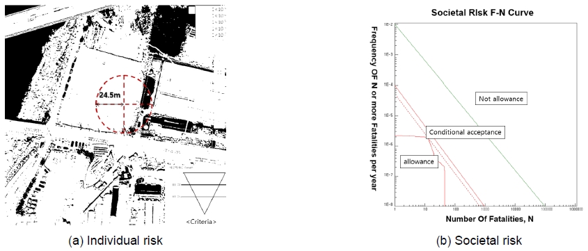
기체수소 자동차충전소 정량적 위험성 평가를 위하여 Hy-KoRam을 사용하여 개인적, 사회적 위험도 산출을 위한 초기 조건을 설정하였다. HAZOP을 통한 화재 폭발 시나리오에 따른 설비별 누출 위치를 정하고 누출공의 크기는 연결배관 단면적의 1%, 10%, 100%12) 누출 방향은 수평 방향으로 100%, 누출 지점은 지상 1 m, 누출 사고 후 차단 조치까지 걸린 시간은 30초로 한다. 수소충전소 위치의 기상은 기상청 날씨누리의 국내 평균값으로 한다. 사람에 대한 위험 복사열은 1.6 kW/m2로, 압력은 70 MPa로 한다. 인구밀도는 현지 조사 결과에 따르며 위험성 평가 모델은 jet fires와 flash fire model을 적용하고 수소 점화 확률은 Table 10을 적용한다13,14). 안전 조치를 통한 위험 빈도 감소는 가스검지기, 긴급차단밸브, 안전밸브 설치 시 반영한다(Fig. 3)10).

The probability of hydrogen ignition (source: Sandia Report 2009-0874, p. 55)

Fig. 3.

Individual risk (a) and societal risk (b) of the compressed hydrogen delivery type

4.2.2 사고 시나리오의 구성

저장식 기체수소 자동차충전소에 대한 설비별 사고 발생 빈도와 사고 피해 영향을 산출하기 위하여 사업소에 설치된 장치 및 시설의 설계압력과 운전 온도, 내부 질량과 각 설비별 관련 누출 빈도 점화 확률을 Hy-KoRam에 입력하여 시나리오별 사고 빈도를 유도하였다.

사고 빈도는 기체수소 수소충전소 표준 모델을 기초로 작성되었으며 위험거리(harm distance)는 Houf 및 Schefer 모델을 사용하여 계산하였다12). 정량적 위험성 평가 대상 설비는 HAZOP를 통해 확인된 수소 누출에 따른 화재 폭발 예상 시나리오가 포함된 node로 선정하였고 각각 수소가 흐르는 단면적의 1%, 10%, 100%로 구분하여 Table 11과 같이 작성되었다12,14).

Accident scenarios of the compressed hydrogen refueling station

4.2.3 법적 안전기준과 위험성 평가를 통한 안전거리 비교 검토

정량적 위험성 평가 결과 개인적 위험도는 기준에서 조건부 허용 영역을 1×10⁻⁶-1×10⁻⁴ (1/year), 허용 영역을 1×10⁻⁶ (1/year) 미만으로 주고 있다. 평가 결과 수소 자동차충전소의 허용 사고 발생 빈도 동일 영역의 중심으로부터 최대 거리가 24.5 m이다.

사회적 위험도 해석을 위하여 개인적 위험도 분석 자료에 수소 자동차충전소 인근 인구밀도 자료를 추가하여 분석하였다. 사회적 위험도는 위험성 평가 결과 판단 기준에서 조건부 허용 영역은 1×10⁻⁴-1×10⁻² (1/year), 허용 영역은 1×10⁻² (1/year) 미만이며 평가 결과는 5×10⁻⁵ (1/year)으로 허용 영역에 포함된다는 것을 알 수 있다. 국내 고압가스안전관리법(이하 고법)에서는 사업소 내 사람을 수용하는 건축물 또는 보호시설과의 거리는 30 m를 요구하고 있어 위험성 평가에서 허용 최대치인 개인적 위험도 5×10⁻⁶ (1/year)을 적용한 거리 24.5 m를 만족하고 있다.

고법에서는 30 m 이내 사람을 수용하는 건축물이 있을 경우 수소 누출에 따른 화재 폭발 피해를 최소화하기 위해 방호벽을 설치하도록 규정하고 있는데 Hy-koRam에서 방호벽을 안전대책에 포함하지 않고 개인적 위험도를 산출한 만큼 법적 안전거리가 적정하다고 볼 수 있다. 또한 수소 누출에 따른 화재 폭발 시나리오를 포함한 node가 고법에서 요구하고 있는 저장, 처리, 압축, 충전 설비와 동일하다. 따라서 본 연구의 위험성 평가와 법적 안전거리의 비교가 유효할 것으로 판단된다. 다만 인구밀도의 변화에 영향을 받는 사회적 위험도의 경우는 주변 환경 변화에 따라 변경될 수 있다.


5. 액화수소 자동차충전소 안전성 평가 결과

5.1 정성적 위험성 평가

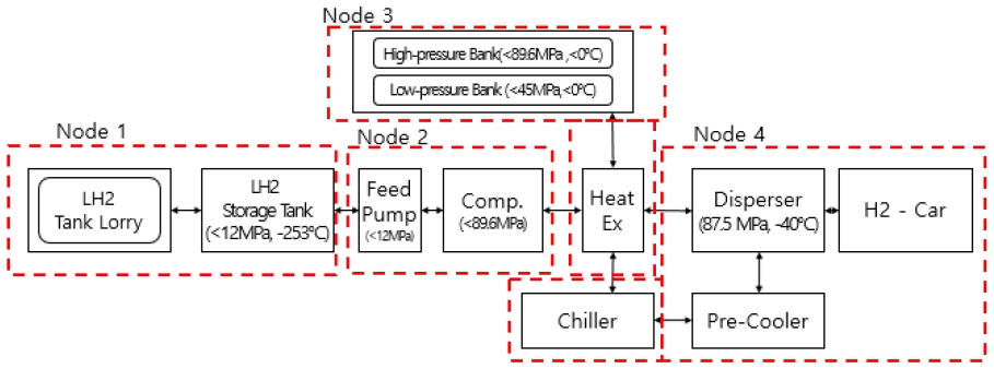
Fig. 4와 같은 구조로 액화수소를 탱크로리로 공급받는 액화수소 자동차충전소 1개소를 대상으로 HAZOP을 이용하여 위험성 평가를 실시하였다. 충전소 설비 node를 Fig. 4와 같이 고법에서 정한 저장, 처리, 충전, 압축가스 설비와 같이 구분하였다. 설계압력 12 MPa, 액체 -253℃인 01 (하역 저장부), 액화수소를 12 MPa에서 89.6 MPa로 가압하는 02 (액화수소 가압부), 기체수소로 상변환시켜 고압과 저압 압축가스 설비에 저장하는 03 (액화수소 열교환부), 설계압력 87.5 MPa, -40℃로 충전하기 위한 04 (기체수소 충전부)로 나누어 HAZOP을 실시하였다. Node는 유체의 형태, 온도, 압력에 따라 구분하였다. Node별 검토 구간과 주요 부품은 Tables 12, 13과 같다. 검토 결과 기록표 중 수소 누출, 화재 폭발이 결과로 이어지는 시나리오를 유사 원인별로 분류하여 안전 조치를 포함하여 위험 등급 3 이상을 분류하여 Table 14와 같이 정리하였다. 주요 이상 원인은 액화수소 설비의 풀림, 체결 불량, 계측오류에 따른 액화수소 과량 공급, 이충전 절차 오류로 인한 이물질 혼입, 단열 진공 파괴, 이로 인한 수소의 대기 누출, 방출, 화재 폭발 등이며 안전 조치는 충전 커플링 개선, 수소가스검지기, 화염검지기 설치, 정기 점검, 고정장치 개선을 포함하였다.

Fig. 4.

Node classification for QRA of refueling station by type of liquid hydrogen delivery

Comparison of QRA results and safety distances within the business site (compressed hydrogen refueling station type)

Results of risk assessment according to node (liquid hydrogen refueling station type)

Fire and explosion scenarios of the liquid hydrogen refueling station

5.2 정량적 위험성 평가

5.2.1 초기 조건

Safeti를 사용하여 액화수소 충전소 정량적 위험성 평가를 수행하였다. 먼저 개인적, 사회적 위험도를 산출하기 위한 초기 조건을 설정하였다. HAZOP을 통해 확인된 시나리오에 따른 설비별 누출 위치를 정하고 설비별 누출공의 크기를 연결배관 단면적의 1%, 10%, 100%12)로, 누출 방향은 수평 방향으로 100%, 누출 지점은 지상 1 m로, 누출 사고 후 차단 조치까지 걸린 시간은 30초로 가정한다.

수소 자동차충전소 위치의 기상은 기상청 날씨누리의 해당 지역 평균값으로 한다. 인구밀도는 현지 조사 결과에 따르며 위험성 평가 모델은 jet fires와 explosion model을 적용한다4). 수소 점화 확률은 Table 15를 적용한다15). 충전 설비 기본 차량의 수는 20대이며 연간 운행 일수는 250일 기준으로 연간 10,000대 충전을 기본 요건으로 한다4). 안전밸브, 수소가스 누출 검지기와 같은 안전장치로 인한 사고 발생 위험 빈도 저감을 반영한다10,16).

Accident scenarios of the liquid hydrogen refueling station

5.2.2 사고 시나리오 구성

액화수소 자동차충전소의 화재 폭발 사고 시나리오별 수소 누출 확률은 정성적 위험성 평가 결과에서 도출된 node별로 설치된 용기, 압축기, 플랜지, 호스, 조인트, 파이프, 밸브 등 부속품에 대한 누출 빈도를 부품의 수량으로 곱하여 전체 빈도를 계산하여 점화 확률을 곱한 빈도로 산출하였다12).

충전 설비의 경우 위험 시나리오를 충전 차량이 충전 호스를 끊고 이동하는 경우와 충전 중 과압이 형성되는 경우에 한하여 누출 직경 크기 100%로 계산한다.

Table 15의 시나리오를 안전기준에서 분류한 저장 설비, 처리 설비, 충전 설비에 대하여 개인적, 사회적 위험도를 계산하였다.

5.2.3 법적 안전기준과 위험성 평가를 통한 안전거리 비교 검토

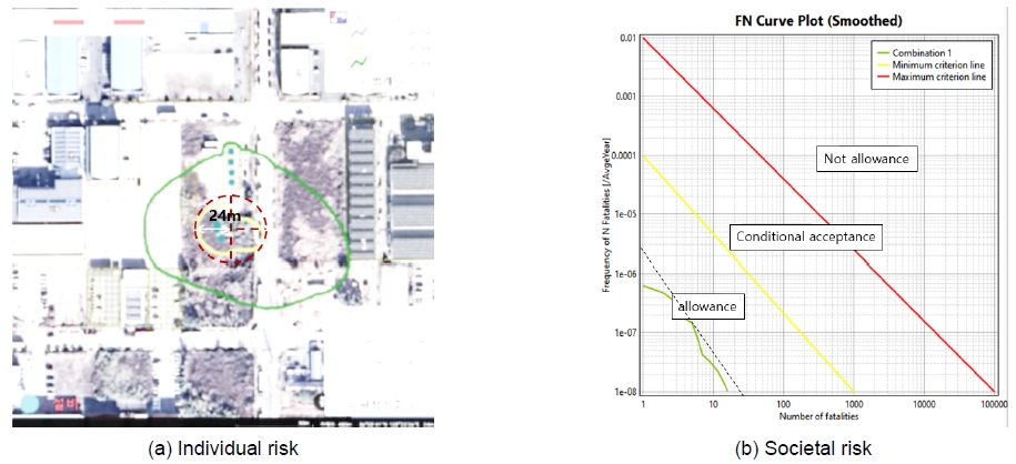
정량적 위험성 평가 결과 개인적 위험도는 Fig. 5와 같이 조건부 허용 영역을 1×10⁻⁶-1×10⁻⁴ (1/year), 허용 영역을 1×10⁻⁶ (1/year) 미만으로 하고 있다14). 평가 대상인 액화수소 자동차충전소는 허용 영역 1×10⁻⁷ (1/year)인 영역이 확인되었다. 영역의 최대 반경이 24 m이며 허용 기준인 1×10⁻⁶ (1/year)보다 빈도가 낮아 기준을 만족하였다.

Fig. 5.

Individual risk (a) and societal risk (b) of the liquid hydrogen delivery type

주변 인구밀도를 고려한 사회적 위험도 조건부 허용영역은 1×10⁻⁴-1×10⁻² (1/year), 허용 영역은 1×10⁻² (1/year) 미만으로 평가 결과 1.5×10⁻⁶ (1/year)은 허용 영역에 해당된다14).

또한 액화수소 자동차충전소의 수소 누출로 인한 화재 폭발 시나리오를 포함한 설비가 고법의 저장, 처리, 압축, 충전 설비와 동일하게 분류되어 있으므로 본 연구의 위험성 평가 결과와 고법에서 요구하고 있는 안전거리와 비교가 가능하다. 다만 액화수소 자동차충전소 주위 인구가 변화할 경우 사회적 위험도는 변경될 수 있다.

국내 액화수소 자동차충전소에 대한 사업소 내 법적 안전거리는 설비로부터 30 m를 요구하고 있으며 방호벽을 설치하면 예외로 둔다.

정성적 위험성 평가 결과는 방호벽 설치를 반영하지 않았고 안전장치 설치로 인한 위험도 저감만을 반영하여 산출한 결과로 1×10⁻⁷ (1/year)은 사고 발생 허용 빈도 기준보다 낮아 법에서 요구한 위험성 평가 결과와 KGS code가 요구한 안전거리 모두를 만족한다(Table 16).

Comparison of QRA results and safety distances within the business site (liquid hydrogen refueling station type)

위험성 평가 허용 기준과 법적 안전거리 요구 사항을 비교한 결과 법에서 요구한 안전거리가 보수적으로 설정되어 있었다.


6. 결론

본 연구에서는 국내 기체수소 자동차충전소와 액화수소 자동차충전소 각각 1개소에 대한 정성적, 정량적 위험성 평가를 실시하였고 국내외 안전기준에서 정한 안전거리와 비교하였다. 기체 수소충전소의 경우 허용 개인적 위험도가 1×10⁻⁶ (1/year), 범위 24.5 m로 고법에 따른 사람을 수용할 수 있는 사업소 내 건물 및 보호시설과의 안전거리 30 m보다 짧다. 사회적 위험도의 경우 허용 기준 1×10⁻⁴ (1/year)보다 낮은 5×10⁻⁵ (1/year)이다. 액화수소 자동차충전소의 경우 개인적 위험도는 1×10⁻⁷ (1/year)의 영역이 24 m로 허용 기준보다 짧고 사회적 위험도도 1×10⁻⁶ (1/year)으로 허용 기준 이하이다.

압축가스 설비, 충전 설비와 수소 누출로 인한 화재 폭발 시나리오 대상 node가 동일하며 고법 안전거리보다 위험성 평가 결과의 위험도 영역의 반경이 짧기 때문에 현재 법에서 요구하고 있는 안전거리는 유효하다고 볼 수 있다. 또한 개인적 위험도 허용 기준 1×10⁻⁶ (1/year)인 영역이 최대 반경이 24.5 m로 해외 기준에서 정한 최대 이격거리 13.8 m보다 짧고 국내 고법의 기준인 30 m보다 짧으며 방호벽과 안전 조치를 통해 위험도를 낮출 수 있는 만큼 추가적인 안전 조치가 실시된 도심지 설치 충전소에 대한 안전거리 축소 연구가 필요할 것으로 판단된다.

References

  • Y. S. Byun, “A study on safety improvement for mobile hydrogen refueling station by HAZOP analysis”, Journal of Hydrogen and New Energy, Vol. 32, No. 5, 2021, pp. 299-307. [https://doi.org/10.7316/KHNES.2021.32.5.299]
  • M. R. Shin, “Risk assessment based on HyRAM on safety distance derivation and risk analysis of hydrogen multi-refueling [Master’s thesis]”, Incheon: Inha University; 2020, pp. 7-10.
  • H. Kim and S. Kang, “Analysis of damage range and impact of on-site hydrogen fueling station using quantitative risk assessment program (Hy-KoRAM)”, Journal of Hydrogen and New Energy, Vol. 31, No. 5, 2020, pp. 459-466. [https://doi.org/10.7316/KHNES.2020.31.5.459]
  • B. Ehrhart, E. Hecht, and B. Schroeder, “Hydrogen plus other alternative fuels risk assessment models (HyRAM+) version 5.1 technical reference manual”, Sandia National Laboratories, 2023, pp. 21-34. [https://doi.org/10.2172/2369637]
  • Korea Gas Safety Corporation (KGS), “Facility/technical/inspection code for fuel vehicles refueling by type of on-site hydrogen production (KGS FP216 2022)”, KGS, 2022, pp. 1-9. Retrieved from https://cyber.kgs.or.kr/kgscode.codeSearch.view.ex.do?onEngYn=F&pblcRlmCd=&pblcMdclCd=&pblcCd=FP216_221230&stDayY=2008&stDayM=01&etDayY=2024&etDayM=10, .
  • Korea Gas Safety Corporation (KGS), “Facility/technical/inspection code for vehicles refueling by type of compressed hydrogen delivery (KGS FP217 2022)”, KGS, 2022, pp. 1-9. Retrieved from https://cyber.kgs.or.kr/kgscode.codeNew.view.ex.do;cyberJSESSIONID=w5DFjoFxXgwKWSLtS9xihu1AgX75BF09Ftvrc6V21xIp4tgM-9iA!-921595914!NONE?pblcCd=FP217_221230&rnum=2, .
  • Korea Gas Safety Corporation (KGS), “Facility/technical/inspection/supervision/safety assessment additional draft code for type liquefied hydrogen Delivery”, KGS, 2023.
  • Korea Gas Safety Corporation (KGS), “Facility/technical/inspection/supervision/safety assessment additional draft code for production of liquefied hydrogen”, KGS, 2023.
  • Ministry of Environment (MOE), “Hydrogen charging station construction manual”, MOE, 2021, pp. 38-40. Retrieved from https://www.me.go.kr/home/web/policy_data/read.do?menuId=10262&seq=7724, .
  • J. Y. Lee, J. Lee and H. Song “A Study on the Analysis of Risk Factors for Hydrogen Fuel Stations Based on Quantitative Risk Assessment” Journal of the Korean Institute of Gas, Vol. 24, No. 6, 2020, pp. 70-76. [https://doi.org/10.7842/kigas.2020.24.6.70]
  • Korea Occupational Safety and Health Agency (KOSHA), “Technical guidelines for continuous process hazards and operation analysis (HAZOP) techniques (KOSHA GUIDE P-82-2023)”, KOSHA, 2023. Retrieved from https://www.kosha.or.kr/kosha/info/searchTechnicalGuidelines.do, .
  • J. LaChance, W. Houf, B. Middleton, and L. Fluer, “Analyses to support development of risk-informed separation distances for hydrogen codes and standards”, Sandia National Laboratories, USA, 2009, pp. 121-130. Retrieved from https://energy.sandia.gov/wp-content/uploads/2018/05/SAND2009-0874-Analyses-to-Support-Development-of-Risk-Informed-Separation-Distances-for-Hydrogen-Codes-and-Standards.pdf, .
  • D. Kwon, S. K. Choi, and C. Yu, “Improved safety by crossanalyzing quantitative risk assessment of hydrogen refueling stations”, International Journal of Hydrogen Energy, Vol. 47, No. 19, 2022, pp. 10788-10798. [https://doi.org/10.1016/j.ijhydene.2021.12.211]
  • Korea Gas Safety Corporation (KGS), “Safety impact assessment guidelines for hydrogen vehicle charging station”, KGS, 2022, pp. 3-7.
  • J. Kim, L. Kim, N. Yoo, B. Choi, and S. Jung, “Quantitative risk assessment of onsite hydrogen refueling station by using HyRAM+, PHAST & SAFETI”, Journal of Energy Engineering, Vol. 33, No. 1, 2024, pp. 1-15. [https://doi.org/10.5855/ENERGY.2024.33.1.001]
  • Korea Occupational Safety and Health Agency (KOSHA), “Technical guidelines on accident damage prediction techniques (KOSHA GUIDE P-102-021)”, KOSHA, 2021. Retrieved from https://www.kosha.or.kr/kosha/info/searchTechnicalGuidelines.do, .
  • S. Jallais and L. Bernard, "Pre-normative research for safe use of liquid hydrogen (PRESLHY)", Fuel Cells and Hydrogen 2 Joint Undertaking, 2018, pp. 10. Retrieved from https://hysafe.info/wp-content/uploads/sites/3/2020/01/PRESLHY-D2.3-LH2-Installation-description_20191119_V1p1.pdf, .
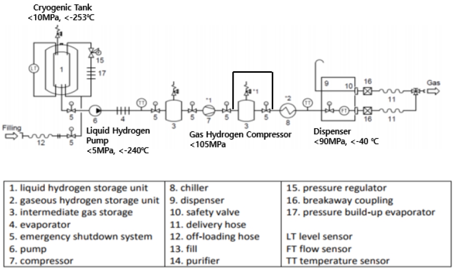
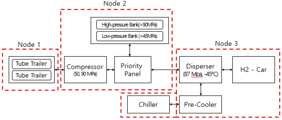
Fig. 1.

Fig. 1.
Schematic of the liquefied hydrogen refueling station17)

Fig. 2.

Fig. 2.
Node classification for QRA of refueling station by type of compressed hydrogen delivery

Fig. 3.

Fig. 3.
Individual risk (a) and societal risk (b) of the compressed hydrogen delivery type

Fig. 4.

Fig. 4.
Node classification for QRA of refueling station by type of liquid hydrogen delivery

Fig. 5.

Fig. 5.
Individual risk (a) and societal risk (b) of the liquid hydrogen delivery type

Table 1.

Status of hydrogen refueling station in Korea (2024)

Type Hydrogen source Number of station
Mobile Container 6
On-site Hydrogen generators using fuel processing technologies 2
Water electrolysis hydrogen generator 1
Off-site Pipe 9
Tube trailer 184
Liquefied hydrogen tank 7
Mixed Tube trailer and hydrogen generators using fuel processing technologies 9
Total 218

Table 2.

Classification of hydrogen refueling stations by supply type

Classification Supply type Supply pressure (design pressure, MPa)
On-site Reformer production Production (<1) → compression (90-105) → compressed gas facility (50-55, 100-105) → refueling (87.5-95)
Water electrolysis production Production (<1) → compression (90-105) → compressed gas facility (50-55, 100-105) → refueling (87.5-95)
Off-site Pipe supply Pipe (<20) → compression (90-105) → compressed gas facility (50-55,100-105) → refueling (87.5-95)
Trailer supply Trailer (<200) → compression (90-105) → compressed gas facility (50-55, 100-105) → refueling (87.5-95)

Table 3.

Classification of hydrogen refueling stations by refueling method

Classification Refueling process (design pressure, MPa)
Differential pressure refueling (Preliminary operation) storage facility (5-20) → compressor (>105) → compressed gas facility (100,50)
(Refueling) compressed gas facility (100,50) → refueling (87.5)
Direct refueling (Refueling) compressor (>100) → compressed gas facility (100,50) → refueling (87.5)
Mixed refueling
(direct + differential pressure)
(Preliminary operation) storage facility (5-20) → compressor (>105) → compressed gas facility (100,50)
(Step 1) compressed gas facility (100,50) → refueling (87.5)
(Step 2) compressor (>900) → compressed gas facility (100,50) → refueling (87.5)

Table 4.

Classification of hydrogen refueling stations by installation type

Classification Subcategories Installation type
Standalone type Fixed type Fixed installation of storage and refueling facilities (on-site, off-site)
Package type Mobile refueling by fixedly installing storage and compression facility in one protective box
Mobile type Mobile refueling by fixedly installing storage and compression facility in a vehicle
Fusion type CNG or LPG vehicle refueling station, gas station + on-site refueling station mixed type
Complex type CNG or LPG vehicle refueling station, gas station + off-site refueling station mixed type

Table 5.

Korea laws to be applied at each stage of construction of hydrogen refueling stations

Construction stage Refueling facility safety codes
Technical review Enforcement regulation of the High Pressure Gas Safety Management Act, Article 7 (Application for Technical Review) Paragraph 1
permission High Pressure Gas Safety Management Act, Article 4 (Permission for Production of High-Pressure Gas) Paragraph 1
Inspection Common (gas + liquefied hydrogen) Enforcement regulation of the High Pressure Gas Safety Management Act, Article 8, Appendix 5
KGS FP 217 2022 (off-site), KGS FP 216 2022 (on-site)
liquefied hydrogen Enforcement Decree of the Industrial Convergence Promotion Act, Article 11

Table 6.

Distances that must be maintained between hydrogen refueling stations and major facilities according to Korean codes

Hydrogen refueling station type Safety distance
Protection facility Separation target Separation distance (m) Note
Standalone or fixed
On-site or off-site
Storage, throughput facility Type 1 protection facility 17-30 Depends on storage and throughput
Type 2 protection facility 12-20
Other gas facilities Combustible gas 10
Oxygen gas 5
Throughput, compressed gas facility Business office boundary 10 (when installing a firewall, 5)
Throughput, compressed gas facility Protective facility, building to accommodate people 30 (excluding when installing a firewall) Building within the business office
Refueling facility Road 5
Gas facility Railroad 30
Standalone or fixed
Off-site
Storage facility Refueling facility (Firewall) or (8 or higher)
Fusion or complex Storage, throughput facility Protection Facility (Firewall) or (8 or higher), safety evaluation results
Gas facility Business office boundary
Refueling facility Road
Gas facility Railroad (30 or higher), safety evaluation results

Table 7.

Overseas status of hydrogen refueling stations safety distances

Separation target Safety distance (m)
Japan (High Pressure Gas Security Act) USA (NFPA 2) UK (BCGA CP 41)
Protection Facility Buildings type 1 and 2: 12-17
Apply detour distance when installing a firewall
3
(refueling location)
8
Firearms Working pressure exceeding 40-82 MPa or less: straight line distance 8
Working pressure 40 MPa or less: straight line distance 6
Detour distance applied when taking flow prevention measures
There is no distance limit when installing an automatic fire extinguisher
13.8 5
Other gas facilities flammability: 6
Oxygen: 10
6.1 5
Business office boundary Working pressure exceeding 40-82 MPa or less: straight line distance 8
Working pressure 40 MPa or less: straight line distance 6
Apply detour distance when installing a firewall
13.8 8
Road boundary Working pressure exceeding 40-82 MPa or less: straight line distance 8
Working pressure 40 MPa or less: straight line distance 6
3
(refueling facility)
8
Railroad boundary No regulations 3
(refueling facility)
No regulations

Table 8.

Results of risk assessment according to node (compressed hydrogen refueling station type)

Node Unit Review section Main components
01 Hydrogen supply unit From hydrogen tube trailer to compressor front end Hydrogen tube trailer
02 Compressed storage unit From the front of the compressor to the back of the compressed gas facility Compressor + compressed gas facility
03 Refueling unit From the compressed gas rear end to the charger Dispenser-cooler-charger

Table 9.

Fire explosion scenarios of the compressed hydrogen refueling station

Node Cause of accident Result Safety measures* Class
*Safety measures: measures to supplement safety equipment to reduce the frequency of personal and social risks
#160;Common safety measures: installation of hydrogen gas detector, flame detector, and explosion-proof electrical equipment/regular inspection, maintenance, compliance with hydrogen refueling protocol
1,2,3 Hose, tube rupture, poor connection of gas equipment parts, instrument damage, valve hydrogen leakage Fire explosion due to hydrogen leak Gas tight test
Installation of high pressure prevention safety valve
High pressure prevention interlock
2
1 The connection part is separated due to abnormal movement of the tube trailer
Damage to pipes, loosening of flanges and couplings due to collisions with tube trailers parking stop
Chock
Refueling manual, driver training
Installation of high pressure blocking device
2
2 Leakage of valves, instruments, and fittings due to vibration caused by malfunction of valves at the front and rear of the compressor
Loosening of connections due to compressor's own vibration
Confirmed by test run
Addition of fixing devices for compressor and front and rear piping
Use of low vibration compressor
3
1,2,3 Leakage due to poor fastening of flanges and connections Daily inspection
Real-time monitoring
3
1,2,3 The valve opens due to aging of the safety valve spring
The valve opens due to an error in the setting value of the safety valve
Safety valve cycle test
Low pressure alarm and interlock
3
2 Abnormal high pressure operation of compressor High pressure/high temperature prevention instrument installation and interlock 3
3 Cracks/breaks in dispenser piping and valves, flow meters, and hoses
Damaged hydrogen pipe in pre-cooler
Check refueling station refueling protocol
Check with pressure gauge
2

Table 10.

The probability of hydrogen ignition (source: Sandia Report 2009-0874, p. 55)

Hydrogen release rate (kg/s) Immediate ignition probability Delayed ignition probability
<0.125 0.008 0.004
0.125-6.25 0.053 0.027
>6.25 0.230 0.120

Table 11.

Accident scenarios of the compressed hydrogen refueling station

Safety code classification Node Component Storage/throughput capacity
(individual)
design pressure
(MPa)
quantity operating Temperature (℃) Mass*
(kg)
scenario
(%)
Leak size (mm)
frequency
(1/year)
Ignition probability
Immediately Delay
*Use Hy-RAM mass calculation program
Storage facility 1 Tube trailer 4,833 m3 20 2 15 342 1 1.27 4.14E-4 0.008 0.004
10 4.02 3.21E-4 0.008 0.004
100 12.70 1.08E-4 0.053 0.027
Throughput facility 2 Compressor
(high pressure)
10,639 m3/day 103.4 2 15 1 1 0.72 9.92E-4 0.008 0.004
10 2.26 2.62E-5 0.008 0.004
100 7.16 4.24E-6 0.053 0.027
Compressed gas facility 2 Middle pressure Storage 1,189 L 50 4 15 33 1 0.79 2.38E-4 0.008 0.004
10 2.50 1.83E-4 0.008 0.004
100 7.92 9.78E-5 0.053 0.027
High pressure Storage 48 L 100 16 15 28 1 0.72 2.38E-4 0.008 0.004
10 2.26 1.83E-4 0.008 0.004
100 7.16 9.78E-5 0.053 0.027
Refueling facility 3 Charger 58,247 m3/day 95 2 -40 25 1 0.72 1.74E-4 0.008 0.004
10 2.26 8.32E-5 0.008 0.004
100 7.16 3.84E-5 0.053 0.027

Table 12.

Comparison of QRA results and safety distances within the business site (compressed hydrogen refueling station type)

Safety code classification Node Component Design
pressure
(MPa)
Safety distance (m)
Houf, Schefer model (a) Risk assessment (b) Korea (c) USA (d)
(a) Calculated excluding safety measures using Sandia 2009 Report Appendix D Hydrogen Facility Risk Model
(b) Quantitative risk assessment results using Hy-KoRam(Based on personal risk 1.00E-06 [1/year])
(c) Based on Enforcement Regulation of the High Pressure Gas Safety Management Act, Article 8, Appendix 5, 30 m from business office buildings (excluding when installing a firewall), 24 m from type 1 protection facility
(d) Refueling facility, road and railway 3 m, business office boundary 13.8 m
Storage facility 1 Tube trailer 20 5.42-54.08 24.5 30 3, 13.8
Throughput facility 2 Compressor
(high pressure)
103.4 6.02-59.82
Compressed gas facility 2 Middle pressure storage 50 5.07-50.48
High pressure storage 100 6.02-59.82
Refueling facility 3 Charger 95 6.02-59.82 24

Table 13.

Results of risk assessment according to node (liquid hydrogen refueling station type)

Node Facility Description of review section Main facilities
01 Storage facility From tank lorry to liquefied hydrogen storage tank Tank lorry, off-road panel, liquefied hydrogen storage tank, refueling hose, connector, valve, vent line, PBUC
02 Compressed throughput facility From the liquefied hydrogen storage tank through the feed pump and high-pressure compressor to the front of the heat exchanger Feed pump, high pressure compressor, recovery line, safety valve, vent line
03 Phase conversion throughput facility From the front end of the heat exchanger to the front end of the high pressure storage vessel Heat exchanger, cold heat recovery facility, safety valve, vent line
04 Refueling facility From high-pressure storage containers to chargers Hydrogen supply panel (control valve), high-pressure storage container, low-pressure storage container, pre-cooler, charger

Table 14.

Fire and explosion scenarios of the liquid hydrogen refueling station

Node Cause Consequence Safety measures* Rank
*Safety measures: measures to supplement safety equipment to reduce the frequency of personal and social risks
 Common safety measures: installation of hydrogen gas detector, flame detector, and explosion-proof electrical equipment/regular inspection and maintenance, compliance with hydrogen charging protocol
1, 4 Poor connection of unloading coupling
Loosening coupling for vehicle refueling
Hydrogen leak and fire explosion BIONET fastening method
Unloading and refueling procedure manual operation and automation
Emergency shutoff valve operation
3
1, 2, 3, 4 Loosening of pipe joints and valves, metal flexible hoses, fittings, and pump connections Pressure resistance, air tightness test
Confirmation of construction by registered professional construction business
Confirmation of fitting worker qualifications
3
1 Exceeded regulatory differential pressure of tank lorry and liquefied hydrogen tank Fire explosion due to hydrogen release into the atmosphere due to excessive supply of liquefied hydrogen Safety valves and vent lines are installed to allow hydrogen to diffuse into the atmosphere without generating flames 3
1 Double vacuum pipe vacuum destruction Hydrogen atmospheric emissions due to the increase in temperature and pressure inside the liquefied hydrogen tank and piping Facility regular inspection and maintenance (vacuum level cycle management)
Installation of a safety valve and atmospheric vent line of sufficient capacity
3
1, 2, 3, 4 Long-term non-use without hydrogen emissions Installation of a safety valve and atmospheric vent line of sufficient capacity
Cycle management of tank vacuum level and insulation condition management
For safety management, measures are taken to release hydrogen and charge nitrogen when not in use
2
1 Vacuum destruction of liquefied hydrogen tank Fire explosion due to hydrogen leakage due to destruction of the inside and outside of the liquefied hydrogen tank
Equipment such as AOV valves cannot be operated due to freezing and air liquefaction
Installation of a large-capacity safety valve to prevent overpressure in the storage tank
Vacuum level monitoring
Storage tank pressure gauge and thermometer installation
Installation of non-combustible materials and insulation materials inside and outside the machine room
2
2 Emergency stop of pump, etc. and valve stop Loosen connection due to pump vibration Safety valve installation 3
4 Lock failure when breaking away from breakaway coupling
Start with vehicle hose installation
Hydrogen leak through refueling hose Emergency shutoff device operation 2
4 Solenoid valve lock failure
Manual valve lock failure
Charger shutdown failure
Hydrogen leak through nozzle
2

Table 15.

Accident scenarios of the liquid hydrogen refueling station

Safety code classification Node Component Quantity Diameter (mm)
Operating Temperature (℃) Scenario Leak size (mm) frequency (1/year) Ignition probability
Immediately Delay
*Leak diameter, size, ignition probability: valve average value
Storage facility or pressurized throughput facility 1, liquefied hydrogen storage tank 1 25.40 -253 1% 2.54 2.08E-5 0.008 0.004
10% 8.03 5.70E-6 0.053 0.027
100% 25.4 1.20E-6 0.053 0.027
2 Valve* 37 22.83 -253 1% 2.28 5.40E-5 0.008 0.004
10% 7.22 2.50E-5 0.032 0.016
100% 22.83 4.80E-6 0.042 0.021
2 Flange 4 22.23 -253 1% 2.22 2.40E-4 0.008 0.004
10% 7.03 2.70E-5 0.031 0.016
100% 22.23 2.90E-6 0.053 0.027
2 Joint 15 15.88 -253 1% 1.59 7.90E-6 0.008 0.004
10% 5.02 7.50E-6 0.031 0.016
100% 15.88 6.40E-6 0.031 0.016
2 Pipe 10 33.02 -253 1% 3.30 9.60E-7 0.008 0.004
10% 10.44 4.60E-7 0.044 0.022
100% 33.02 1.50E-7 0.053 0.027
Phase transformation throughput facility 3 Valve 4 14.29 <0 1% 1.43 5.40E-5 0.019 0.010
10% 4.52 2.50E-5 0.053 0.027
100% 14.29 4.80E-6 0.186 0.097
Joint 4 25.40 <0 1% 2.54 7.90E-6 0.053 0.027
10% 8.03 7.50E-6 0.053 0.027
100% 25.4 6.40E-6 0.230 0.120
Heat exchanger 4 19.05 <0 1% 1.91 5.76E-6 0.053 0.027
10% 6.02 2.76E-6 0.053 0.027
100% 19.05 9.00E-7 0.230 0.120
Refueling facility 4 Valve 4 14.29 <0 100% 14.29 6.29E-5 0.186 0.097

Table 16.

Comparison of QRA results and safety distances within the business site (liquid hydrogen refueling station type)

Safety code classification Node Component Design pressure (MPa) Safety distance (m)
Risk assessment (a) Korea (b) USA (c)
(a) Quantitative risk assessment results using Safeti (based on personal risk 1.00E-07 [1/year])
(b) Based on Enforcement regulation of the High Pressure Gas Safety Management Act, Article 8, Appendix 5, 30 m from business office buildings (excluding when installing a firewall), 24 m from type 1 protection facility
(c) Refueling facility, road and railway 3 m, business office boundary 13.8 m
Storage facility 1 Hydrogen tank lorry 1 24 30 3, 13.8
Throughput facility 2 Compressor (low pressure) 3
Compressor (high pressure) 100
Heat exchanger 100
Compressed gas facility 2 High pressure storage 103
Refueling facility 3 Charger 95 24