고분자 전해질 연료전지용 SPEEK 막의 어닐링에 의한 화학적 내구성 향상
2023 The Korean Hydrogen and New Energy Society. All rights reserved.
Abstract
Hydrocarbon-based polymer membranes to replace perfluorinated polymer membranes are being continuously researched. However, hydrocarbon-based membranes have a problem in that they are less durable than fluorine-based membranes. In this study, we sought to compare the annealing effect to improve the durability of sulfonated poly(ether ether ketone) (SPEEK). After membranes formation, thermogravimetric analysis and tensile strength were measured to compare changes in membranes properties due to annealing. After manufacturing the membrane and electrode assembly (MEA), the initial performance and chemical durability was compared with unit cell operation. During the 24-hour annealing process, the strength increased due to the increase in –S–O–S-crosslinking, and the sulfonic acid group decreased, leading to a decrease in I-V performance. By annealing, the hydrogen permeability was reduced to less than 1/10 of that of the nafion membrane, and as a result, open circuit voltage (OCV) and durability was improved. The SPEEK membranes annealed for 24 hours showed higher durability than the nafion 211 membranes of the same thickness.
Keywords:
PEMFC, SPEEK, Durability, Annealing, Chemical degradation, OCV holding키워드:
고분자 전해질 연료전지, 술폰화 폴리에테르 에테르 케톤, 내구성, 어닐링, 화학적 열화, 개회로 전위 유지1. 서 론
유해물질 배출이 없으며 높은 효율을 가지고 있는 연료전지는 청정에너지로, 현재 문제가 되고 있는 에너지 및 환경 문제를 동시에 해결할 수 있는 대체에너지이다. 그런데 고분자 전해질 연료전지(polymer electrolyte membrane fuel cell, PEMFC)의 고분자 막은 과불소 술폰산(perfluorosulfonic acid) 막을 사용해 문제가 되고 있다1). 인류의 건강과 환경에 악영향을 주는 과불소 알킬기 소재들에 대해 국제적인 조사와 규제가 증가되고 있는 상황이다2,3). 예를 들어 유럽연합(European Union, EU)은 2030년까지 이런 과불소계 소비재들에 대해 단계적 폐지를 목표로 하고 있다4). 따라서 과불소계 고분자 막을 대체할 탄화수소계 고분자 막들이 꾸준히 연구되고 있다. 대표적으로 sulfonated poly(ether ether ketone) (SPEEK), sulfonated poly(arylene ether), poly(arylene ether ketone), poly-benzimidazole, polyimide 등이 비불소 탄화수소계 고분자 막들이다5-8). 탄화수소계 막은 친환경적이라는 장점 이외에도 저가여서 저비용 연료전지를 가능하게 하며 연료전지 시장을 확대하는 데 기여할 수 있다. 하지만 기술적으로 해결해야 할 점들이 있는데, 저가습 조건에서 성능을 향상시켜야 하고, 내구성을 향상시켜야 하는 점 등이다.
고분자 막 제조 시 제막 과정에서 열처리는 용매를 제거하는 건조 단계(dry step)와 안정성을 확보하기 위한 어닐링 단계(annealing step)로 구성된다. 고분자 막의 안정적인 성능과 내구성을 위해서는 어닐링 과정이 중요하다. Mugtasimova 등9)은 Aquivion류의 막을 160-170℃에서 어닐링했을 때 Nafion NR 211보다 더 높은 이온전도도를 얻었다고 하였다. Vengatesan 등10)은 Nafion 20% solution을 150℃에서 3-12시간 동안 열처리했을 때 6시간에서 제일 높은 I-V 성능을 보였다. Li 등11)은 Nafion NRE 211 H-form 막을 160℃ 이하에서 어닐링하면 습도 유도 응력이 감소한다고 했다. Park 등12)은 Nafion 복합막이 190℃에서 2시간 어닐링하면 이온전도도가 더 증가한다고 하였다. Moore와 Martin13)과 Moore III와 Martin14)은 Nafion 이오노머를 120-250℃에서 어닐링하면 물리적 거동이 향상된다고 하였다. 그리고 Luan 등15)은 과불소 술폰산 이오노머(perfluoro-sulfonated ionomer)를 150-230℃ 범위에서 어닐링했을 때 온도가 상승할수록 막의 함수율과 메탄올 투과도가 감소함을 보였다. 내구성 향상을 위해서 어닐링 방법이 불소계 막들에 적용되었는데, SPEEK 막은 PEMFC나 direct methanol fuel cell의 성능 향상에만 적용된 상황이다13,14,16).
고분자 막의 열화는 전기화학적 열화(electrochemical degradation)와 기계적 열화(mechanical degradation)로 크게 분류된다17). 전기화학적 열화는 셀 내에서 발생하는 라디칼이 고분자 막을 공격해 핀홀이나 크랙이 형성되어 고분자 막이 열화되는 현상이다. 기계적 열화는 가습(wet)/건조(dry)에 의해 고분자 막이 수축/팽창되기를 반복함에 따라 기계적 응력을 받아 고분자 막이 찢어지면서 열화되는 현상이다18). 고분자 막의 내구 평가 시간을 단축하기 위해 미국 에너지부(United States Department of Energy, DOE)와 일본 신에너지 산업기술 개발기구(New Energy and Industrial Technology Development Organization, NEDO)에서는 가속 내구 평가(accelerated stress test, AST) 기법을 사용한다19). 전기화학적 AST로 라디칼이 많이 발생하는 고온, 저가습 조건에서 open-circuit voltage (OCV) holding 방법으로 고분자 막의 내구성을 평가하고 있다20,21).
본 연구에서는 PEMFC용 SPEEK 막의 어닐링에 의한 전기화학적 내구성 변화에 대해 DOE의 전기화학적 가속 내구 평가법을 적용해 검토하였다.
2. 실 험
2.1 SPEEK 막 및 membrane and electrode assembly (MEA) 제조
SPEEK는 poly(ether ether ketone) (450PF; Victrex, Lancashire, UK)과 진한 황산(95%; Samchun Chemical, Seoul, Korea)을 1 g 대 25 mL의 비율로 원형 플라스크에 넣어 대기압, 25℃ 항온조에서 60시간 동안 교반하여 술폰화시킨 후, 얼음물이 담긴 수조에 용액을 부어 고체화된 고분자를 얻었다. 그 후, pH 5-6 사이가 될 때까지 증류수 세척을 진행하고, 50℃ 오븐에서 24시간 건조시켜 SPEEK 고분자를 제조하였다22,23).
SPEEK 막은 앞서 제조된 SPEEK과 dimethylacetamide (DMAc, 99.5%; Samchun Chemical)를 SPEEK과 DMAc 질량 기준 1:9로 하여 바이얼에 넣고, 4-50℃ 핫플레이트에서 2-3시간 교반하여 모두 용해시킨 다음 유리판에 약 250 µm의 두께로 캐스팅한 뒤, 50℃ 오븐에서 4-6시간 건조 후, 140℃에서 일정 시간 어닐링하고 유리판에서 떼어내어 제막을 완료하였다. 제막한 SPEEK 막의 두께는 25 µm으로 내구성 평가에 사용했다.
SPEEK MEA는 SPEEK 막 양면에 데칼 방법을 이용하여 Pt/C 전극 입자를 코팅해 연료극과 공기극 모두 Pt 함량 0.4 mg/cm2로 제조하였다24). 이때 전극 접착 온도는 120℃였으며, 촉매와 막 사이의 접착제 역할을 하는 바인더는 불소계 바인더인 Nafion ionomer (5wt% Nafion resin solution; Sigma-Aldrich, St. Louis, MO, USA)를 이용했다.
2.2 SPEEK 막의 특성 측정
어닐링에 따른 SPEEK 막의 강도 변화를 분석하기 위해 MEA 전 막 상태에서 인장 강도를 측정하였다. 인장 강도는 texture analyzer (TAXTplus, Stable Micro System, Godalming, UK)를 이용하였으며, 시편 크기는 1.0×2.0 cm로 3회 측정한 후 평균값을 얻었다.
그리고 thermogravimetric analysis (TGA, Q50; TA Instruments, New Castle, DE, USA)로 25-800℃의 질소 분위기에서 유속 50 mL/min, 가열 속도 10℃/min로 진행하였다.
MEA의 성능 및 전기화학적 특성은 I-V 분극곡선, 수소 투과 전류 밀도(hydrogen crossover current density, HCCD), 단락 저항(short resistance)을 측정하여 비교하였다16,17).
I-V 분극곡선은 연료극과 공기극에 각각 수소(1.5 Stoi.)와 공기(2.0 Stoi.)를 공급하고, 전류 변화에 따른 전압을 loader로 측정하였다.
HCCD는 Potentiostat (SI 1287; Solartron, West Sussex, UK)을 이용한 linear sweep voltammetry (LSV) 방법으로 수소 투과 전류(hydrogen crossover current)를 측정해 비교하였다. LSV는 연료극과 공기극에 각각 수소(40 mL/min)와 질소(200 mL/min)를 공급하고, 주사 속도 1 mV/s로 0.0-0.4 V 범위에서 전압을 변화시키면서 전류를 측정하였다. DOE 기준에 의해 0.3 V에서 전류밀도를 HCCD로 결정하였다.
단락 저항은 LSV 측정 데이터로부터 산출하였다. 0.4-0.5 V 구간에서 직선의 기울기를 구한 후 이 기울기의 역수를 SPEEK MEA의 단락 저항이라 하였다.
2.3 MEA 열화 가속화 실험
전기화학적 전해질 막 가속 열화 실험은 다음과 같이 실시하였다. 전극 면적이 9 cm2 인 MEA를 단위전지에 체결하고 단위전지 온도, 유량, 상대습도(relative humidity, RH) 등을 PEMFC test station (CNL Energy Co.; Seoul, Korea)을 이용하여 제어하였다. 고분자 막의 전기화학적 내구 평가 방법인 OCV holding을 cell 90℃, anode RH 30%, cathode RH 30% 조건에서 H2 347 mL/min과 공기 829 mL/min을 각각 anode와 cathode에 주입하여 가속 내구 평가를 진행하였다. OCV holding 진행 시 중간마다 활성화 후 I-V와 LSV의 측정을 통해 MEA의 성능을 확인하고 OCV holding을 반복하여 어닐링이 MEA의 내구성에 미치는 영향을 비교하였다.
3. 결과 및 고찰
3.1 SPEEK 막의 특성 분석 및 MEA 초기 성능
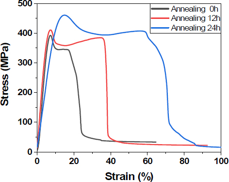
SPEEK 막의 인장 강도를 측정하여 Fig. 1과 Table 1에 나타냈다. 전체적으로 어닐링한 막의 강도가 증가한 것을 볼 수 있다. 특히 24시간 어닐링한 SPEEK 막의 stress (yield stress, ultimate stress)와 strain (yield strain, ultimate strain) 모두 12시간 어닐링한 막에 비해 급증했다. 이와 같은 결과는 고분자 사슬 간에 S-O-S 교차 연결이 어닐링 시간이 길어지면서 증가해서, 인장 응력이 가해져도 막이 찢어지지 않고 견뎌내는 강도가 증가한 것이다24).
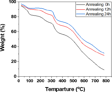
어닐링 온도에 따라 제조된 고분자 막의 TGA를 Fig. 2에 나타냈다. 100℃까지의 무게 감소는 SPEEK 막 내에서 H2O의 증발에 의한 것이라 할 수 있는데, 어닐링하지 않은 막이 어닐링한 막에 비해 2배 이상 무게 감소가 많다. 145℃ 어닐링 온도에서 물이 증발한 결과를 보면, 100-200℃에서 무게 감소는 술폰산기에 흡수된 물의 분리에 의한 것인데, 어닐링하지 않은 막과 12시간 어닐링한 막의 해당 온도 구간에서 무게 감소량은 비슷하나, 24시간 어닐링한 막의 무게 감소는 이들에 비해 작다. 이와 같은 결과는 24시간 어닐링 과정 중 슬폰산기가 -S-O-S- crosslinking이 발생했기 때문이라고 본다24,25).
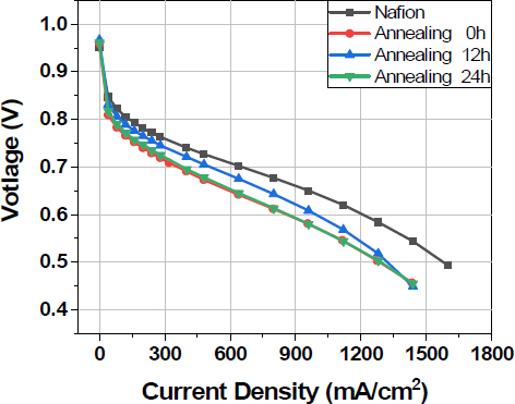
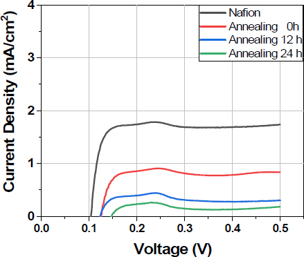
SPEEK 고분자를 이용하여 어닐링에 의해 내구성을 향상시키고자 하였다. 어닐링으로 안정화된 고분자 막을 제막 후 MEA를 제조하여 성능 및 전기화학적 특성을 비교하였다. Fig. 3의 I-V 분극곡선과 Table 2에서 나타낸 것처럼 12시간 어닐링 OCV는 0.967 V로 어닐링하지 않은 MEA에 비해 1.0% 증가하였는데, HCCD의 감소 영향도 있다고 본다(Fig. 4). 12시간 어닐링한 MEA는 0.6 V에서의 전류 밀도가 991 mA/cm2로 어닐링하지 않은 MEA에 비해 15.1% 증가하여 어닐링에 의한 막의 이온전도도 향상이라고 판단한다. 12시간 어닐링한 MEA의 HCCD는 0.31 mA/cm2로 어닐링하지 않은 MEA의 38%로 감소하였다. 어닐링하지 않은 막도 불소계 막 Nafion 211에 비해 수소 투과도가 낮지만, 어닐링에 의해 수소 투과도를 더 감소시켰고 그 결과 OCV가 증가한 것이다. 24시간 어닐링한 SPEEK 막의 HCCD가 같은 두께의 Nafion 211 막보다 10% 이하로 작다. 수소 투과도가 낮을수록 PEMFC 구동 조건에서 수소 투과로 인한 라디칼 형성이 적기 때문에 전해질 막의 전기화학적 내구성 향상에 도움이 된다26,27).
3.2. OCV holding에 의한 내구성 평가
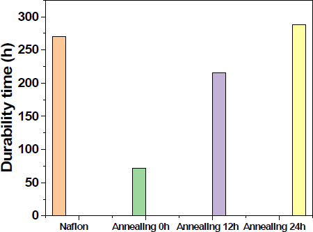
어닐링한 고분자막의 전기화학적 내구성을 평가하기 위해 MEA 제조 후 단위전지에 체결하여 OCV holding하였고, 그 과정에서의 LSV 변화를 Fig. 5에 나타냈다. 고분자 막이 라디칼에 의해 열화되면서 얇아지고 그에 따라 수소 투과도가 증가하는데, HCCD가 급증하면 OCV holding을 종료하였고, 종료 시점을 Fig. 6에 비교하였다. Fig. 6에서 SPEEK 막을 어닐링하여 내구성이 향상되었음을 볼 수 있다. 24시간 어닐링한 SPEEK 막은 같은 두께의 Nafion 211 막보다 내구성이 더 높다. 탄화수소계 막이 불소계 막보다 내구성이 약한 것이 문제였는데, 화학적 내구성은 탄화수소계 막이 불소계 막보다 더 높다. 이와 같은 결과는 SPEEK 막의 수소 투과도가 Nafion 막보다 10% 이하여서 라디칼 발생 속도가 작기 때문이다. 동일한 라디칼 발생 속도일 경우 SPEEK막이 불소계 막보다 내구성이 약했겠지만, SPEEK 막의 낮은 수소 투과도가 SPEEK 막의 내구성을 향상시켰다.
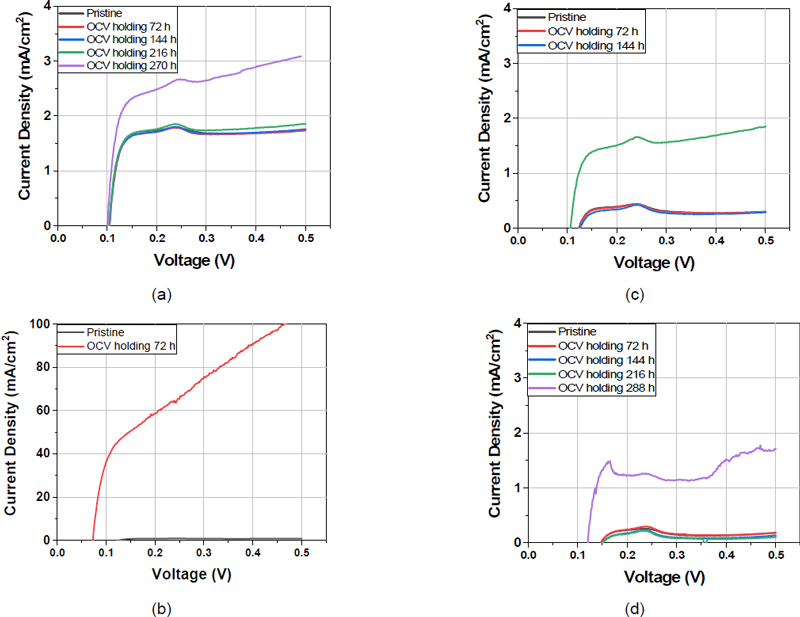
LSV change of (a) Nafion 211, (b) without annealing SPEEK, (c) 12 hours annealing SPEEK, (d) 24 hours annealing SPEEK during OCV Holding
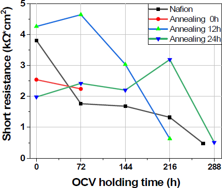
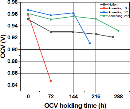
Fig. 5에서 수소 투과도가 급증하는 시점에 단락저항이 1.0 kΩ·cm2 이하가 됨을 Fig. 7에서 볼 수 있다. DOE의 고분자막 전기화학적 내구 평가 기준은 HCCD가 15 mA/cm2 이상이거나, OCV 감소가 20% 이상 또는 short 저항이 1.0 kΩ·cm2 이하이다28). 그러나 탄화수소계 막에서 HCCD가 15 mA/cm2 이상이 되면 MEA가 연소될 수 있는 위험한 상태이므로 이는 적합한 기준이 아니고, NEDO의 HCCD 10배 기준이 더 적합하다29). OCV 변화를 Fig. 8에 나타냈는데 수소 투과도가 급증하는 시점에는 모두 OCV 감소가 컸지만 초기보다 20% 이상 감소하지는 않았다. 내구성이 다한 평가 종료 시점을 HCCD와 OCV 감소의 값으로 정하는 어려움을 SPEEK 막의 화학적 AST 과정에서 명확해졌다. Short 저항은 내구 평가 종료 시점 즉, 내구성 정량적 값을 명확히 나타내는 매우 중요한 측정값이다. 그러나 불소계 막의 내구성은 주로 HCCD로 측정되었는데, 연구 결과 탄화수소계 막에서는 HCCD보다 short 저항이 더 중요한 지표로 사용되어야 할 것으로 보인다.
4. 결 론
PEMFC용 탄화수소계 SPEEK 막의 내구성 향상을 위해 제막 후 140℃에서 열처리(어닐링)한 결과를 정리하면 다음과 같다.
1) 어닐링한 SPEEK 막의 강도가 증가하였다. 어닐링 과정에서 형성된 고분자 사슬 간에 S-O-S 가교 결합이 어닐링 시간이 길어지면서 증가해서 인장 응력이 가해져도 막이 찢어지지 않고 견뎌내는 강도가 증가하였다. 24시간 어닐링 과정에서 S-O-S 가교결합 증가에 따라 슬폰산기의 감소하고, 슬폰산기에 흡수된 물의 양이 감소하며, 이는 막의 이온전도도 감소에 따른 I-V 성능 감소로 이어졌다.
2) 어닐링에 의해 수소 투과도를 Nafion 막보다 10% 이하로 감소시켰고 그 결과 OCV가 감소하였다. 수소 투과도가 낮을수록 PEMFC 구동 조건에서 수소와 산소 투과로 인한 라디칼 형성이 작아지기 때문에 SPEEK 막의 전기화학적 내구성을 향상시켰다.
3) 24시간 어닐링한 SPEEK 막은 같은 두께의 Nafion 211 막보다 내구성이 더 높았다. 탄화수소계 막이 불소계 막보다 내구성이 약한 것이 문제로 알려져 있었는데, 열처리에 의해 탄화수소계의 화학적 내구성이 불소계 막보다 더 높아져서 PEMFC 불소계 막을 탄화수소계 막으로 대체할 수 있는 가능성을 보였다.
Acknowledgments
본 과제(결과물)는 2023년도 교육부의 재원으로 한국연구재단의 지원을 받아 수행된 지자체-대학 협력기반 지역혁신 사업의 결과입니다(2021RIS-002).
References
-
S. H. Mirfarsi, A. Kumar, J. Jeong, M. Adamski, S. McDermid, B. Britton, and E. Kjeang, “High-temperature stability of hydrocarbon-based Pemion® proton exchange membranes: a thermo-mechanical stability study”, International Journal of Hydrogen Energy, Vol. 50, Pt. B, 2024, pp. 1507-1522.
[https://doi.org/10.1016/j.ijhydene.2023.07.236]

-
G. Goldenman, M. Fernandes, M. Holland, T. Tugran, A. Nordin, C. Schoumacher, and A. McNeill, “The cost of inaction: a socioeconomic analysis of environmental and health impacts linked to exposure to PFAS”, Nordic Council of Ministers, 2019.
[https://doi.org/10.6027/TN2019-516]

- Joint Subcommittee on Environment, Innovation, and Public Health; Per- and Polyfluoroalkyl Substances Strategy Team, “Per- and polyfluoroalkyl substances (PFAS) report”, National Science and Technology Council, 2023. Retrieved from https://www.whitehouse.gov/wp-content/uploads/2023/03/OSTP-March-2023-PFAS-Report.pdf, .
-
H. Brunn, G. Arnold, W. Körner, G. Rippen, K. G. Steinhäuser, and I. Valentin, “PFAS: forever chemicals-persistent, bioaccumulative and mobile. Reviewing the status and the need for their phase out and remediation of contaminated sites”, Environmental Sciences Europe, Vol. 35, 2023, pp. 20.
[https://doi.org/10.1186/s12302-023-00721-8]

-
M. Xu, H. Xue, Q. Wang, and L. Jia, “Sulfonated poly(arylene ether)s based proton exchange membranes for fuel cells”, International Journal of Hydrogen Energy, Vol. 46, No. 62, 2021, pp. 31727-31753.
[https://doi.org/10.1016/j.ijhydene.2021.07.038]

-
T. Higashihara, K. Matsumoto, and M. Ueda, “Sulfonated aromatic hydrocarbon polymers as proton exchange membranes for fuel cells”, Polymer, Vol. 50, No. 23, 2009, pp. 5341-5357.
[https://doi.org/10.1016/j.polymer.2009.09.001]

-
C. Zhang, S. Kang, X. Ma, G. Xiao, and D. Yan, “Synthesis and characterization of sulfonated poly(arylene ether phosphine oxide)s with fluorenyl groups by direct polymerization for proton exchange membranes”, Journal of Membrane Science, Vol. 329, No. 1-2, 2009, pp. 99-105.
[https://doi.org/10.1016/j.memsci.2008.12.021]

-
J. Zhang, D. Aili, S. Lu, Q. Li, and S. P. Jiang, “Advancement toward polymer electrolyte membrane fuel cells at elevated temperatures”, Research, 2020.
[https://doi.org/10.34133/2020/9089405]

-
K. R. Mugtasimova, A. P. Melnikov, E. A. Galitskaya, I. A. Ryzhkin, D. A. Ivanov, and V. V. Sinitsyn, “Effect of annealing on proton conductivity of aquivion-like proton-exchange membrane”, Key Engineering Materials, Vol. 869, 2020, pp. 367-374.
[https://doi.org/10.4028/www.scientific.net/KEM.869.367]

-
S. Vengatesan, E. Cho, H. J. Kim, and T. H. Lim, “Effects of curing condition of solution cast Nafion® membranes on PEMFC performance”, Korean Journal of Chemical Engineering, Vol. 26, No. 3, 2009, pp. 679-684.
[https://doi.org/10.1007/s11814-009-0113-y]

-
J. Li, X. Yang, H. Tang, and M. Pan, “Durable and high performance Nafion membrane prepared through high-temperature annealing methodology”, Journal of Membrane Science, Vol. 361, No. 1-2, 2010, pp. 38-42.
[https://doi.org/10.1016/j.memsci.2010.06.016]

-
J. S. Park, M. S. Shin, S. S. Sekhon, Y. W. Choi, and T. H. Yang, “Effect of annealing of nafion recast membranes containing ionic liquids”, Journal of the Korean Electrochemical Society, Vol. 14, No. 1, 2011, pp. 9-15.
[https://doi.org/10.5229/JKES.2011.14.1.009]

-
R. B. Moore and C. R. Martin, “Procedure for preparing solution-cast perfluorosulfonate ionomer films and membranes”, Analytical Chemistry, Vol. 58, No. 12, 1986, pp. 2569-2570.
[https://doi.org/10.1021/ac00125a046]

-
R. B. Moore III and C. R. Martin, “Chemical and morphological properties of solution-cast perfluorosulfonate ionomers”, Macromolecules, Vol. 21, No. 5, 1988, pp. 1334-1339.
[https://doi.org/10.1021/ma00183a025]

-
Y. Luan, Y. Zhang, H. Zhang, L. Li, H. Li, and Y. Liu, “Annealing effect of perfluorosulfonated ionomer membranes on proton conductivity and methanol permeability”, Journal of Applied Polymer, Vol. 107, No. 1, 2008, pp. 396-402.
[https://doi.org/10.1002/app.27070]

-
M. Lee, S. Oh, Y. Park, D. Yoo, and K. Park, “Effect of annealing temperature on the durability of PEMFC polymer membrane”, Korean Chemical Engineering Research, Vol. 60, No. 1, 2022, pp. 7-11.
[https://doi.org/10.9713/kcer.2022.60.1.7]

-
S. velan Venkatesan, C. Lim, S. Holdcroft, and E. Kjeang, “Progression in the morphology of fuel cell membranes upon conjoint chemical and mechanical degradation”, Journal of The Electrochemical Society, Vol. 163, No. 7, 2016, pp. F637-F643.
[https://doi.org/10.1149/2.0671607jes]

-
B. Wu, M. Zhao, W. Shi, W. Liu, J. Liu, D. Xing, Y. Yao, Z. Hou, P. Ming, J. Gu, and Z. Zou, “The degradation study of Nafion/PTFE composite membrane in PEM fuel cell under accelerated stress tests”, International Journal of Hydrogen Energy, Vol. 39, No. 26, 2014, pp. 14381-14390.
[https://doi.org/10.1016/j.ijhydene.2014.02.142]

-
X. Z. Yuan, H. Li, S. Zhang, J. Martin, and H. Wang, “A review of polymer electrolyte membrane fuel cell durability test protocols”, Journal of Power Sources, Vol. 196, No. 22, 2011, pp. 9107-9116.
[https://doi.org/10.1016/j.jpowsour.2011.07.082]

-
F. D. Coms, H. Xu, T. McCallum, and C. Mittelsteadt, “Mechanism of perfluorosulfonic acid membrane chemical degradation under low RH conditions”, ECS Transactions, Vol. 64, No. 3, 2014, pp. 389-402.
[https://doi.org/10.1149/06403.0389ecst]

- T. Kim, J. Lee, H. Lee, T. W. Lim, and K. Park, “Degradation of polymer electrolyte membrane under OCV/low humidity vonditions”, Korean Chemical Engineering Research, Vol. 45, No. 4, 2007, pp. 345-350. Retrieved from https://koreascience.kr/article/JAKO200710103499700.page, .
-
C. Zhao, X. Li, Z. Wang, Z. Dou, S. Zhong, and H. Na, “Synthesis of the block sulfonated poly(ether ether ketone)s (S-PEEKs) materials for proton exchange membrane”, Journal of Membrane Science, Vol. 280, No. 1-2, 2006, pp. 643-650.
[https://doi.org/10.1016/j.memsci.2006.02.028]

-
H. R. Lee, S. H. Lee, B. C. Hwang, I. C. Na, J. H. Lee, S. J. Oh, and K. P. Park, “Characteristics of proton exchange membr-ane fuel cells(PEMFC) membrane and electrode assembly(MEA) using sulfonated poly(ether ether ketone) membrane”, Korean Chemical Engineering Research, Vol. 54, No. 2, 2016, pp. 181-186.
[https://doi.org/10.9713/kcer.2016.54.2.181]

-
J. Fu, J. Ni, J. Wang, T. Qu, F. Hu, H. Liu, Q. Zhang, Z. Xu, C. Gong, and S. Wen, “Highly proton conductive and mechanically robust SPEEK composite membranes incorporated with hierarchical metal–organic framework/carbon nanotubes compound”, Journal of Materials Research and Technology, Vol. 22, 2023, pp. 2660-2672.
[https://doi.org/10.1016/j.jmrt.2022.12.118]

-
P. Knauth, H. Hou, E. Bloch, E. Sgreccia, and M. L. Di Vona, “Thermogravimetric analysis of SPEEK membranes: thermal stability, degree of sulfonation and cross-linking reaction”, Journal of Analytical and Applied Pyrolysis, Vol. 92, No. 2, 2011, pp. 361-365.
[https://doi.org/10.1016/j.jaap.2011.07.012]

-
J. Song, S. Kim, B. Ahn, J. Ko, and K. Park, “Effect of electrode degradation on the membrane degradation in PEMFC”, Korean Chemical Engineering Research, Vol. 51, No. 1, 2013, pp. 68-72.
[https://doi.org/10.9713/kcer.2013.51.1.68]

-
J. Jeong, M. Song, H. Chung, I. Na, J. Lee, H. Lee, and K. Park, “Performance and durability of PEMFC MEAs fabricated by various methods”, Korean Chemical Engineering Research, Vol. 52, No. 5, 2014, pp. 558-563.
[https://doi.org/10.9713/kcer.2014.52.5.558]

- United States Department of Energy (DOE), “Multi-Year Research, development, and demonstration plan”, DOE, 2016. Retrieved from https://www.energy.gov/sites/default/files/2017/05/f34/fcto_myrdd_fuel_cells.pdf, .
- New Energy and Industrial Technology Development Organization (NEDO), “Cell Evaluation and Analysis Protocol Guideline”, NEDO, 2016. Retrieved from https://www.nedo.go.jp/english/index.html, .
