Modularization and Application of Hybrid Renewable Energy Process in Seosan Area
2023 The Korean Hydrogen and New Energy Society. All rights reserved.
Abstract
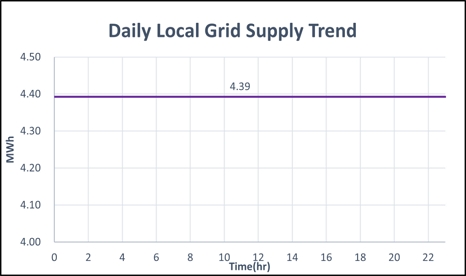
This study presents a modularized process of a hybrid renewable energy system that combines photovoltaic power and wind power to supply stable power in a unit area (1 km²). The water electrolysis process and fuel cells process also contributes to the supply of the stable power. The entire system can constantly supply power of 4.39 MW/km². Actual meteorological data is used for simulation.
Keywords:
Photovoltaic-wind power system, Modularization of hybrid renewable energy system, Stable power supply, Fuel cell, P2G, Simulation키워드:
태양광-풍력 발전, 혼합 신재생에너지 시스템 모듈화, 안정적 전력 공급, 연료전지, 에너지 가스 변환, 모사1. Introduction
As the global warming issue arise, the role of renewable energy has become more important. Recently, more companies have practiced environmental, social and governance (ESG) management in worldwide. Also, lots of companies are participating in 100% of renewable energy (RE100). RE100 is a voluntary campaign that companies will purchase or self-produce all the electricity they need from renewable energy by 2050. Although there is no internationally agreed definition of renewable energy, it mainly refers to energy generated from solar heat, solar power, bio, wind power, hydropower, and geothermal heat. RE100 was launched in 2014 by The Climate Group and Carbon Disclosure Project, a multinational non-profit organization in London, UK. Currently, global companies such as Google, Nike, and IKEA are participating. As for domestic companies, 14 companies including SK Group, Amorepacific Corporation, KB Financial Group, Korea Zinc Corporation, and Korea Water Resources Corporation are participating in RE100.
In 2020, South Korea announced the ‘2050 carbon neutral promotion strategy.’ The industrial structure must change from high-carbon to low-carbon, and the energy used must change from coal to renewable energy. In 2018, South Korea's greenhouse gas emissions peaked at 727.0 million tons of CO2eq1). Although it is expected to decrease from this highest point, it is expected that it will take 30 years to become carbon-neutral. The amount of renewable energy generated in 2020 was 43,062 GWh2). It means 7.43% of the total power generation. Therefore, the supply of renewable energy should increase, and efficient production should be possible.
Among the status of domestic companies participating in RE100, Samsung Electronics currently uses less than 1% of renewable energy. In order to implement RE100 and 2050 carbon neutral promotion strategy, more renewable energy is needed3). Therefore, the purpose of this study is to compensate the short-comings of renewable energy generation and supply stable power. The process simulation is conducted in AVEVA process simulation (APS) based on Seosan area and Daegwallyeong area.
2. Technical assessments
2.1 Process scheme
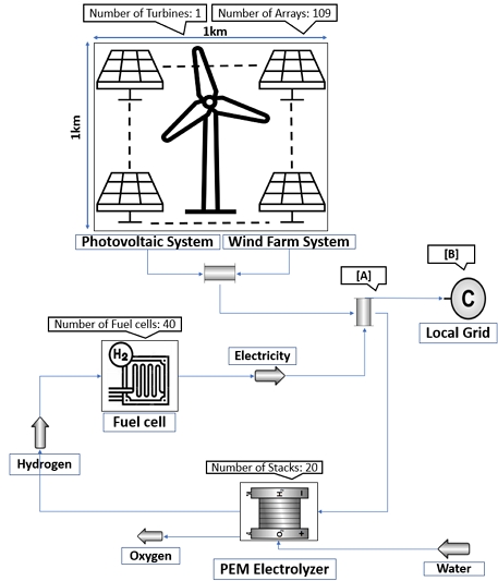
Required power supply [A]: the maximum amount of power that can be constantly produced considering daily production amount of the photovoltaic (PV)-wind power system.
Actual power supply [B]: the amount of actual power that can be supplied to the local grid considering cable efficiency.
The entire process flow proceeds in four steps, following Fig. 1. PV-wind power system, hydrogen production using water electrolysis, power generation using fuel cells, and power supply to the local grid. Based on Seosan area, the process flow is described as follows.
PV-wind power system generates power on a unit area. The unit area is set to 1 km². If the amount of power produced by the system is greater than [A] MW, it moves to the water electrolysis process to produce hydrogen. For the water electrolysis, at least 1 MW of power must be supplied to keep process running. 1 MW is a fixed value even if the size of the entire process (hybrid renewable energy system) increases, excluding the indication of power transfer from the process flow.
If the amount of power produced by PV-wind power system is less than [A] MW, production of hydrogen from the water electrolysis process in the previous time period is used. The hydrogen moves to fuel cells process to generate additional power.
Through this step, the amount of power produced by PV-wind power system is constant with [A] MW. After the steps, considering cable efficiency, [B] MW of power is supplied to the local grid.
2.2 Assumptions and condition
In the entire process (hybrid renewable energy system), the following conditions were assumed.
1) The unit area is set by combining PV power system and wind power system in 1 km².
2) Efficiency in the process is calculated considering only power generation efficiency.
3) The area for simulation is Seosan, where many industrial plants are located in Korea.
4) Through modularization of the entire process, it can be applied to other regions, Daegwallyeong.
5) Carbon neutrality is satisfied through the entire process.
For PV power system, Hi-Mo5 from China's Longi Green Energy, the No. 1 module producer as of 2020, is used. In PV power system requiring large-scale power generation, inverters with the largest output should be selected4). Therefore, Hyosung Heavy Industries' inverter is used in Table 1.
The method of obtaining the number of series and parallel of an array through the specifications of PV panels and inverters are as follows.
Number of PV module series sheet (Sn) is calculated using power conditioner direct current (DC) input voltage and maximum output operating voltage of module. Divide power conditioner DC input voltage by maximum output operating voltage of module comes 20 serials.
Number of PV module parallel sheet is calculated using system output power, maximum output of module, and Sn divide system output power by (maximum output of module) × Sn comes 92 parallels.
Therefore, the rated output capacity for the each converter of PV power system is 828,000 W, using 1,840 sheets of 450 W modules.
In PV panels, shadows act as resistance, so it need to have the right separation distance between cells5).
| (1) |
x1 is the array minimum separation distance, tilt is the array inclination angle, and lat is the latitude of the installation area (Eq. 1).
The module length is 2.256 m and is calculated using the values in Table 2. For the convenience of calculation and the area limited during actual installation, it is assumed to be 4.5 m². Therefore, 1 km²/4.5 m²/piece=2,222,222 pieces, and if the area of inverters and wind turbines is excluded, 200,000 modules can be installed per unit area, 1 km².
Wind Power system can be built in large-scale complexes due to free location constraints, and has high energy efficiency due to excellent wind quality. Since the average wind speed of 80 m Korea Meteorological Agency data is 4-8 m/s6), Doosan Enerbility wind turbine is selected as the superstructure after considering the values of two values: cut-in wind speed, which is the wind speed at which power generation begins, and rated wind speed, which is the wind speed when power generation is maximum7), and the detailed value is presented by the values summarized in Table 3.
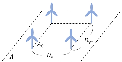
The unit area, A is an area in which a total of four wind turbines are installed in Fig. 2, having the same separation distance as the next turbine in all directions according to Table 48). To indicate the capacity density, multiply by 4 per unit area after 1 km²/A. Therefore, 0.99 power plants can be built per 1 km²/A, and the capacity density of 0.99 wind turbines of 8 MW is 7.92 MW/km². This is also in line with the capacity density of 8 MW/km² proposed by the European Environmental Agency (2009).
For water electrolysis process, polymer electrolyte membrane water electrolysis (PEMWE) can be operated from 25℃ to 90℃. So it is easy to form conditions for hydrogen production even at relatively low temperatures. PEMWE can be operated at a relatively wide current density about 6,000-20,000 A/m², so it can be linked with a renewable energy system9). The renewable energy system has the characteristic of rapidly changing the power produced according to the external environment such as weather. The load responsiveness of water electrolysis according to the instantaneous sudden change and produced power has a strength as the operating range of current density is wide.
For fuel cells process, using a molten carbonate fuel cell (MCFC) to convert hydrogen into power. MCFC is suitable for large-scale power generation and has a high power generation efficiency of about 80%. On average, each MCFC produces 250 kW of power. The power generated by hydrogen is calculated to 66 Wh. The calculation process is given below.
| (2) |
| (3) |
| (4) |
| (5) |
n is number of electrons participating in the reaction, F is Faraday constant, E is electromotive force (Eq. 2). It can be seen that 66 Wh of power is generated per 1 mol of hydrogen (Eq. 5).
Accurate meteorological data is required to make more accurate predictions through the process simulation. For accurate meteorological data, 10 years of data provided by the Korea Meteorological Administration are collected and averaged.
Since the wind turbine is located 80 m above the ground, the provided wind speed data must be converted to the 80 m height of it. Therefore, from the wind speed data at a height of 10 m, the data at 80 m are converted using the Deacon formula (Eq. 6)10). U2 means wind speed at calibrated altitude, Z2 means altitude at calibrated altitude (Eq. 6). U1 means actual measured wind speed at 10 m, and Z1 means actual measured altitude from the anemometer at 10 m (Eq. 6). Also, Zg means geometric average altitude, and Z0 means roughness altitude of surrounding topographic features (Eqs. 8, 9).
| (6) |
| (7) |
| (8) |
| (9) |
Power to gas (P2G) technology is used to compensate for the unstable power generation of renewable energy system and supply stable power11). If hydrogen is produced excessively, power loss occurs due to low efficiency of water electrolysis and fuel cells. On the other hand, if hydrogen is produced less, the production of hydrogen is insufficient, making it impossible to supply constant power. Therefore, it is necessary to calculate and supply the most efficient and optimal amount of power supply.
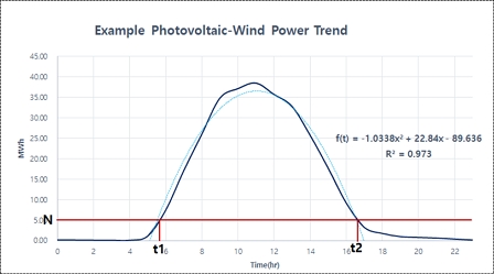
The calculating method is based on the trend line in the range from sunrise to sunset, following Fig. 3.
| (10) |
| (11) |
| (12) |
- f : Conversion efficiency
- P : Total power production perday
- A : Remaining power after moved to local grid
- N : Necessary amount of power supply
By substituting the values obtained through APS into the above equation (Eqs. 10-12), the constant necessary amount of power supply N can be obtained.
In the case of the necessary amount of power supply for wind power system, N cannot be estimated through the graph, unlike PV-wind power system or PV power system. Therefore, the necessary amount of power supply should be calculated in a different way. It is calculated in the following sequence.
1) The necessary amount of power supply is calculated using the amount of wind power system generated per hour.
2) Since wind power system generates at all times, the minimum amount of power generation is known.
3) Subtract the minimum amount of power generation from the amount of power generation for all time zones.
4) The amount of wind power generated through 1-3 process is called reduced amount of wind power, R. 14.73 kg/hr of hydrogen is produced per 1 MWh of power going to water electrolysis, and the hydrogen consumption to generate 1 MWh of power in the fuel cell is 46.09 kg/hr.
5) Calculate the hydrogen consumption and hydrogen production according to each situation by setting an arbitrary N in the order of decreasing a certain amount, like decreasing by 0.01 MWh, from the maximum power generation in R.
6) An appropriate N value is a section in which hydrogen production is greater than hydrogen consumption by a certain amount or more.
7) By adding R and N, the necessary amount of power supply for wind power system is known.
2.3 Process description
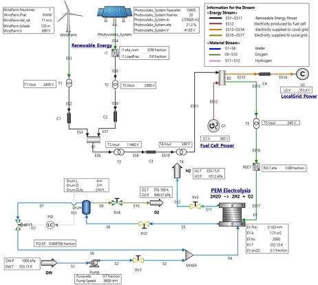
Flow of the entire process consists of four different progress, following Fig. 4. Individual descriptions are written below.
Regarding the flow of the ES1-ES11 process, meaning the flow of power produced by PV and wind power system. The generated power is stored in B2.
At B2, the generated power is distributed into two parts. Regarding the flow of the ES13 to ES14 process, part of the power goes to the local grid. For the flow of the ES15 to ES17 process, remaining power goes to the water electrolysis process.
Regarding the flow of the S11-S12 process, the hydrogen is produced and stored. The significance of the water electrolysis process lies in being able to convert the produced hydrogen back into power.
For the flow of the ES12 process, hydrogen is converted back into power through fuel cells. As the distributed power is combined, a constant power supply to the local grid becomes possible.
2.4 Application to other regions
The simulation process is based on the meteorological data of Seosan area. The same process simulation was conducted in the other region, Daegwallyeong. The reasons for choosing these two regions are as follows.
Seosan has many industrial complexes and is close to industrial complexes, so it is advantageous to introduce the process. In the coastal area of Seosan, the wind speed is almost constant, but in inland areas such as Daegwallyeong, the wind speed is fast during the day. In order to find out whether it is efficient in a region with a different weather trend from Seosan, the process simulation is also conducted in Daegwallyeong12). By comparing the simulation results of the two regions, the feasibility of the process can be confirmed.
2.5 Meteorological data graph for Seosan and Daegwallyeong
The following are meteorological data trends for Seosan and Daegwallyeong. Compared to PV power system, wind power system shows a large difference in utilization rate depending on the region, and both regions have high wind speeds.
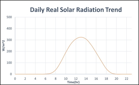
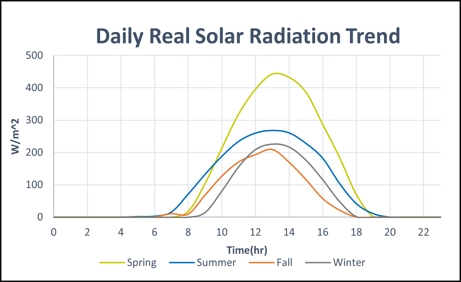
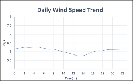
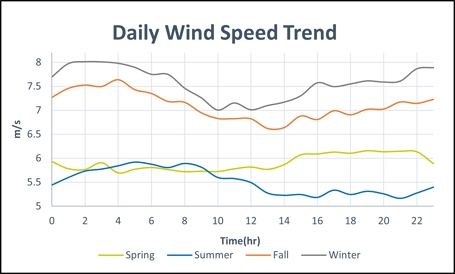
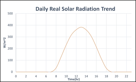
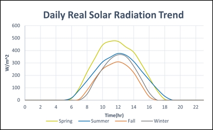
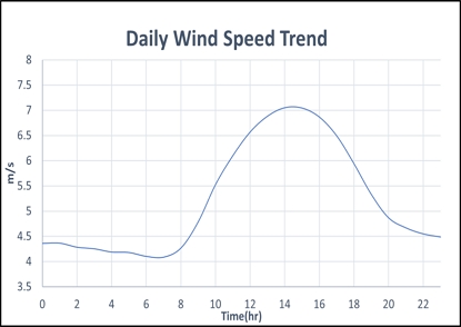
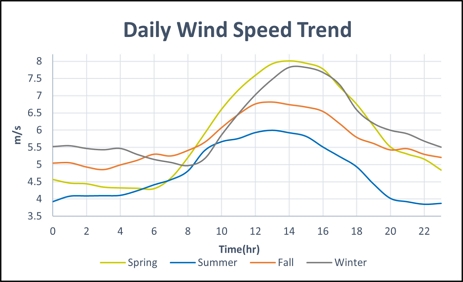
Data of Figs. 5, 6 are from Korea Meteorological Administration, automated synoptic observing system data13) of Korea Meteorological Administration National Climate Data Center. Data of Figs. 7, 8. are from ocean data buoy data14).
The annual average and seasonal trends of real solar radiation are following Figs. 5, 6.
The annual average and seasonal trends of wind speed are following Figs. 7, 8.
Data of Figs. 9-12 are from Korea Meteorological Administration, automated synoptic observing system data13) of Korea Meteorological Administration National Climate Data Center.
The annual average and seasonal trends of real solar radiation are following Figs. 9, 10.
The annual average and seasonal trends of wind speed are following Figs. 11, 12.
3. Results and discussion
3.1 Simulation results in Seosan area
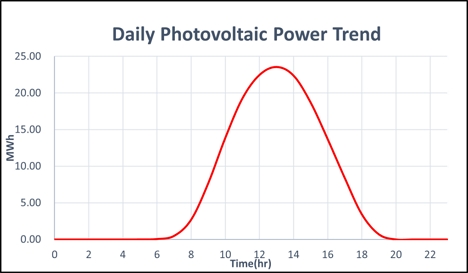
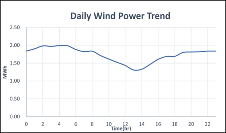
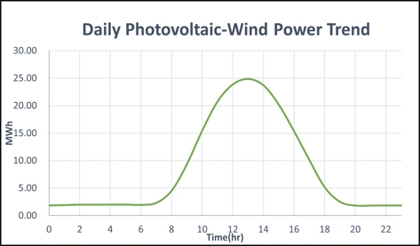
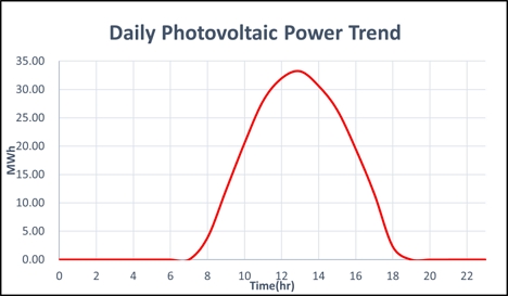
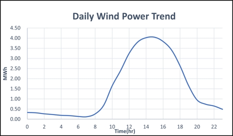
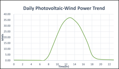
The value of each graph used the average value in the simulation process. Figs. 13, 14 are the daily production of power trend for the PV and wind power system. As PV power system can’t be performed at night, wind power system offsets the disadvantages of the PV power system, following Fig. 1515).
Annual power production for the PV power system, wind power system, and PV-wind power system are placed in Table 5.
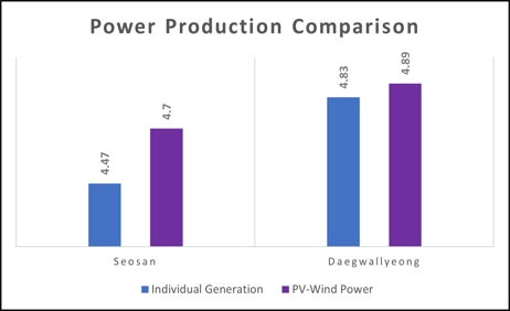
If each system generates power, required power supply for the each system follows Table 616). For the PV power system, it requires 2.87 MWh. For the wind power system, it requires 1.60 MWh. Overall, 4.47 MWh of the power is needed. On the other hand, for the PV-wind power system requiring 4.70 MWh, increases efficiency of 5.22%.
Since the cable efficiency is 1.07, 4.7 MWh of supply power is supplied to the local grid at 4.7 MWh/1.07=4.39 MWh.
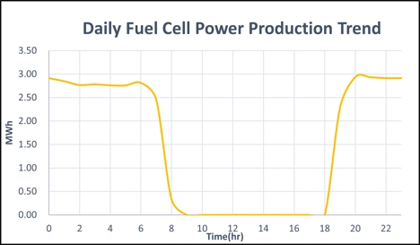
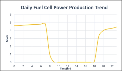
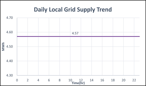
By Fig. 16, as fuel cell system is used to supply constant power, 4.39 MWh of the power is continuously supplied to the local grid, following Fig. 17. Also, the power is calculated considering cable efficiency.
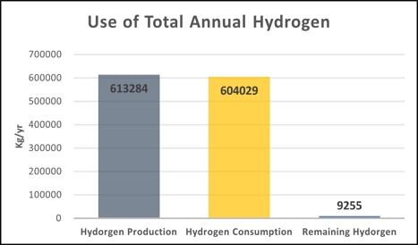
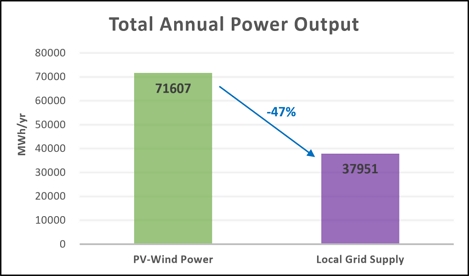
Annual amount of hydrogen remained is 9,255 kg/yr, and the total annual power output of the process is 37,951 MWh/yr, following Figs. 18, 19.
Compared to the actual power produced, local grid supply shows a decrease of about 47%. This is based on the characteristics of renewable energy system17). It is not constant in power generation, but 47% of power loss occurs in the process of making renewable energy constant.
PV-wind power is produced constant through the same process as in 2.2.4, and power loss occurs in the process of power transfer, water electrolysis, and fuel cells.
Since the meteorological condition varies by season according to the characteristics of the Korean Peninsula, not only annual meteorological data but also seasonal meteorological data are used to increase the reliability of the result data18). Each case of the power system, the required power supply is calculated and compared as Table 719).
3.2 Simulation results in Daegwallyeong area
Figs. 20, 21 show the daily power trend output of PV and wind systems in the Daegwallyeong area, respectively. In the case of wind power trend, unlike Seosan, it soars at a certain time, but the impact on the overall trend is insignificant20), following Fig. 22. Therefore, the same method as in Seosan can be used. This concludes the modularized process can be used regardless of the wind trend21).
By Fig. 23, as fuel cell system is used to supply constant power, 4.57 MWh of the power is continuously supplied to the local grid, following Fig. 24. Also, the power is calculated considering cable efficiency.
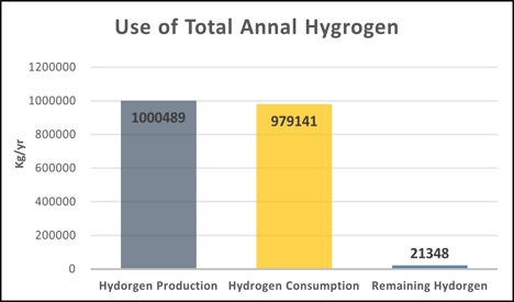
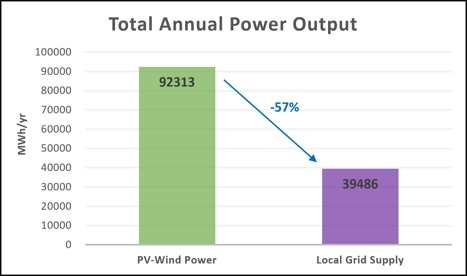
Annual amount of hydrogen remained is 21,348 kg/yr, and the total annual power output of the process is 39,486 MWh/yr, following Figs. 25, 26.
Daegwallyeong area showed a 10% larger reduction in power supply compared to the total power production than Seosan. This is because wind power trends are not constant. This shows that the more constant the wind trend, the lower the power loss.
3.3 Discussion
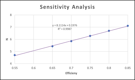
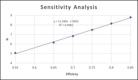
Figs. 27, 28 show the change in N value according to water electrolysis and fuel cells efficiency. Since the efficiency of water electrolysis and fuel cells change similarly, it is assumed that the efficiency of water electrolysis and fuel cells change equally.
If the efficiency is improved to 85%, the N value increases by 51.28% in Seosan and 73.91% in Daegwallyeong on an annual average basis, following Figs. 27, 28. In particular, when an efficiency of about 79% is achieved, corresponding to the 50 kWh/kg-H2 set as the 2030 technology development target in the hydrogen technology development roadmap, it is predicted that the N value can be increased to 8.00 MW in Daegwallyeong and 6.61 MW in Seosan. Therefore, it shows that as the efficiency increases, the efficiency of the water electrolysis and fuel cells increases linearly compared to the same power production, and the power generation efficiency improves. The power generation efficiency can be greatly improved when the efficiency of water electrolysis and fuel cells is improved through research and development of materials and separators for water electrolysis and fuel cells22).
The entire process can be applied to Samsung Pyeongtaek Campus, following Table 9. As of 2020, the required power for the company is 1,426 MW.
Using our modularized process, 122 km² of the area is required for carbon reduction by 2030, using 40% of electricity from renewable energy. For satisfying carbon neutrality by 2050, using 100% renewable energy, 303 km² of the area is required23).
This study aims to supply stable power by using P2G technology for the unstable power generation of renewable energy system. The amount of power generation according to meteorological data is obtained through APS. Using equations and Excel program, calculating the stable power supply is possible.
As a result, it is confirmed that using both wind power and PV power together can produce more power than using them separately, following Fig. 29.
4. Conclusions
This study proposed a modularized system using a PV-wind power system in conjunction with P2G technology (water electrolysis, fuel cells) as a complement to the intermittent power generation characteristics of renewable energy system. Power generation depends on environmental conditions such as solar radiation and wind speed. As a result of performing dynamic simulation for Seosan and Daegwallyeong areas using the Korea Meteorological Administration data and APS, conclusions as follows.
1) In the case of using PV-wind power system, the water electrolysis system utilization rate becomes 100% regardless of time. It leads to stable hydrogen production and efficiency is higher than that of the existing single renewable energy system.
2) It is possible to supply constant power to the local grid by converting hourly excess power into hydrogen using the water electrolysis system and storing it. By converting it back into power using the fuel cells.
3) Through the sensitivity analysis, as the efficiency of the water electrolysis system increases, the amount of power supplied to the local grid increases. This means a highly efficient water electrolysis system is required.
4) Presenting the total amount of power required using a modularized process, it is possible to estimate the area required for a plant design.
5) To supply 100 MW of power using the presenting process, an area of 18.00 km² is required based on Seosan.
References
- Ministry of Environment, “National Greenhouse Gas Inventory Report of Korea”, Ministry of Environment, 2021. Retrieved from https://me.go.kr/home/web/public_info/read.do?pagerOffset=0&maxPageItems=%2010&maxIndexPages=10&searchKey=all&searchValue=&menuId=10123&orgCd=&condition.deleteYn=N&publicInfoId=1294&menuId=10123, .
- Korea Energy Agency New & Renewable Energy Center, “2020 New & Renewable Energy Supply Statistics”, Korea Energy Agency, 2021. Retrieved from https://www.knrec.or.kr/biz/pds/statistic/view.do?no=120, .
-
J. S. Oh and K. J. Jo, “A study on solar-wind hybrid power generation system”, Journal of Advanced Marine Engineering and Technology, Vol. 33, No. 8, 2009, pp. 1226-1231. Retrieved from https://www.dbpia.co.kr/journal/articleDetail?nodeId=NODE01293488, .
[https://doi.org/10.5916/jkosme.2009.33.8.1226]

- Y. Shin, S. Baek, B. Hwang, J. Lim, and K. Kim, “Current situation and utilization-rate as of both solar and wind power-plant in Korea”, Korean Electrical Society academic papers, 2011, pp. 303-305. Retrieved from https://www.dbpia.co.kr/journal/articleDetail?nodeId=NODE01798342, .
- Solar Energy Research Society, “Solar photovoltaic power generation system”, Munundang, Korea, 2015, pp. 71-73.
-
J. W. Lee, K. K. Ko, and K. K. Lee, “The effect of power generation capacity and wind speed on the efficiency of the Korean wind farms”, Korean Management Science Review, Vol. 30, No. 2, 2013, pp. 97-106.
[https://doi.org/10.7737/KMSR.2013.30.2.097]

- B. E. Koh, S. J. Moon, and H. Yoo, “Comparison between expected and actual capacity factors of a wind farm”, Plant Journal, Vol. 7, No. 1, 2011, pp. 40-48. Retrieved from https://koreascience.kr/article/JAKO201117558397791.page, .
-
N. J. Choi, S. H. Nam, J. H. Jeong, and K. C. Kim, “CFD study on aerodynamic power output of 6 MW offshore wind farm according to the wind turbine separation distance”, Journal of Advanced Marine Engineering and Technology, Vol. 35, No. 8, 2011, pp. 1063-1069.
[https://doi.org/10.5916/jkosme.2011.35.8.1063]

- H. S. Shin, “Prediction of PEM Electrolyser system operating characteristics by applying the analysis of mass transport phenomena [Doctoral dissertation]”, Gwangju: Chonnam National University; 2020, pp. 30-56.
- Korea Meteorological Administration Data Management Service Team, “Wind resource map development research report”, Korea Meteorological Administration, 2007. Retrieved from https://policy.nl.go.kr/search%20/searchDetail.do?rec_key=SH1_UMO20150208472&kwd, .
-
S. Jeong, N. H. Choi, C. Moon, S. Moon, and H. Lim, “Economic feasibility analysis for P2G using PEM water electrolysis”, Journal of Hydrogen and New Energy, Vol. 28, No. 3, 2017, pp. 231-237.
[https://doi.org/10.7316/KHNES.2017.28.3.231]

-
S. Jeon, S. An, Y. Choi, and H. Sung, “A Study on the site selection for wind power using GIS”, New & Renewable Energy, Vol. 7, No. 3, 2011, pp. 83-91. Retrieved from https://www.kci.go.kr/kciportal/ci/sereArticleSearch/ciSereArtiView.kci?sereArticleSearchBean.artiId=ART001590209, .
[https://doi.org/10.7849/ksnre.2011.7.3.083]

- Korea Meteorological Administration (KMA)National Climate Data Center, “Automated Synoptic Observing System (ASOS)”, KMA, 2023. Retrieved from https://data.kma.go.kr/data/grnd/selectAsosRltmList.do?pgmNo=36, .
- Korea Meteorological Administration (KMA) National Climate Data Center, “Marine Meteorological Observation Buoy Data”, KMA, 2023. Retrieved from https://data.kma.go.kr/data/sea/selectBuoyRltmList.do?pgmNo=52, .
-
K. Kim and J. Kim, “The optimal design and economic evaluation of a stand-alone RES energy system for residential, agricultural and commercial sectors”, Korean Chemical Engineering Research, Vol. 54, No. 4, 2016, pp. 470-478.
[https://doi.org/10.9713/kcer.2016.54.4.470]

- T. G. Kim, “Performance analysis with respect to fuel and temperature change in a molten carbonate fuel cell [master's thesis]”, Daejeon: Hanbat University; 2016, pp. 14-56.
-
H. Hwang, J. Moon, and J. Kim, “Economic benefits of integration of supplementary biopower and energy storage systems in a solar-wind hybrid system”, Korean Chemical Engineering Research, Vol. 58, No.3, 2020, pp. 381-389.
[https://doi.org/10.9713/kcer.2020.58.3.381]

-
D. K. Jo, Y. Heack, and Y. C. Park, “Analysis of solar radiation climate in Korea”, Proceedings of ISES World Congress, Vol. 1-5, 2009, pp. 8-11.
[https://doi.org/10.1007/978-3-540-75997-3_460]

-
D. S. Jeoune, J. Y. Kim, H. G. Kim, J. Kim, C. Youm, and K. Y. Shin, “Development of economic evaluation solution and power prediction of renewable energy system”, Journal of the Korean Solar Energy Society, Vol. 39, No. 6, 2019, pp. 93-112.
[https://doi.org/10.7836/kses.2019.39.6.093]

-
J. Woo, H. J. Lee, and S. Y. Huh, “Forecasting solar photovoltaic and wind power deployment in South Korea: an innovation diffusion approach”, KSEE, Vol. 31, No, 1, 2022, pp. 16-29.
[https://doi.org/10.5855/ENERGY.2022.31.1.016]

- K. S. Kim, “Technology Trends of Photovoltaic Modules Applicable to Power Coversion Devices for Photovoltaic Modules”, KIPE Magazine, Vol. 20, No. 3, 2015, pp. 47-52. Retrieved from https://www.dbpia.co.kr/journal/articleDetail?nodeId=NODE06363384, .
-
S. Hwang and J. N. Park, “Techno-economic analysis of water electrolysis system connected with photovoltaic power generation”, Journal of Hydrogen and New Energy, Vol. 32, No. 6, 2021, pp. 477-482.
[https://doi.org/10.7316/KHNES.2021.32.6.477]

-
J. Park, C. H. Kim, H. S. Cho, S. K. Kim, and W. C. Cho, “Techno-economic analysis of green hydrogen production sys-tem based on renewable energy sources”, Journal of Hydrogen and New Energy, Vol. 31, No. 4, 2020, pp. 338-344.
[https://doi.org/10.7316/KHNES.2020.31.4.337]

