Numerical Model Development of a Microchannel Condenser for Mobile Air-Conditioning Systems
2022 The Korean Hydrogen and New Energy Society. All rights reserved.
Abstract
This paper presents the numerical model development of a microchannel heat exchanger in mobile air-conditioning and heat pump applications. The model has been developed based on the effectiveness-NTU method using a segment-by-segment modeling approach. State-of-art correlations are used for refrigerant- and air-side heat transfer coefficients and pressure drops. The calculated heat condenser capacities are in good agreement with experimental data, with an average difference of 1.86%. The current model can be used for microchannel condenser simulations under various operating conditions. It is anticipated to improve productivity in designing and optimizing microchannel heat exchangers with folded louver fin geometry.
Keywords:
Condenser, Microchannel heat exchanger, Louver fin, Numerical model, R134a키워드:
응축기, 마이크로채널 열교환기, 루버핀, 수치적 모델1. Introduction
Microchannel heat exchangers (MCHE) are widely used in mobile and residential air-conditioning applications. The desire to improve efficiency and reduce refrigerant charge drove their introduction into heating, ventilation, and air conditioning (HVAC) systems. Recent advancements in nano or microscale fabrication techniques have resulted in significant progress on MCHE. In general, one of the main challenges in heat exchanger design is achieving a high heat transfer rate in small volumes. Because of their advantages, MCHEs are the most promising design to meet this challenge. When compared to round tube plate-fin heat exchangers, flat tubes allow for better airflow over the tubes. Improved airflow can help to reduce the power required by the fan as well as the heat transfer resistance.
However, with the reduction of the hydraulic diameter, a different flow regime and heat transfer mechanism occur in the microchannel than in the conventional channels1). As a result, determining fluid flow and heat transfer characteristics during refrigerant condensation in microchannels is increasingly essential for condenser performance. In the literature, some numerical studies have been conducted to better understand the thermal properties of condensation inside microchannels.
Several researchers have conducted experimental and numerical research on MCHEs to improve system performance2-7). In the automotive industry, microchannel condensers are typically limited to a single synthetic working fluid (e.g., R-134a) operating in a narrow range of saturation temperatures (30-60°C). Empirical models for this narrow range of operating conditions could be developed and used for MCHE design and optimization.
Several researchers8-11) simulated R134a condensation inside mini and microchannels. Da Riva and Del Col8) considered the effects of interfacial shear stress, gravity, and surface tension for horizontal tube orientation before repeating the simulations for vertical tube orientation with and without gravity. They went on to look into R134a condensation using the volume of fluid (VOF) method. This time, they simulate with and without surface tension to investigate the effect of surface tension in their simulation conditions9). Ganapathy et al.10) also proposed a numerical model based on VOF for simulating R134a condensation in a 100 μm microchannel. Bortolin et al.11) ran steady-state numerical simulations of R134a condensation inside a 1 mm square minichannel. The simulations used the VOF approach to track the vapor-liquid interface during condensation. The authors concluded that gravity has a minor effect in the square minichannel and that shear stress and surface tension dominate the heat transfer mechanism at the considered mass flux.
Among the various geometric parameters, the effects of microchannel cross-sectional shapes on heat exchanger performance have been extensively studied. The effects of microchannel cross-sectional shapes on the fluid flow and heat transfer performance of rectangular, triangular, and trapezoidal microchannels were investigated numerically by Gunnasegaran et al.12), Wang et al.13), and Chen et al.14). According to Gunnasegaran et al.12) and Wang et al.13), cross sectional areas with small hydraulic diameters have low thermal resistance and pressure drop. Furthermore, it was discovered in both studies12,13) that rectangular-shaped microchannels performed best while triangular-shaped microchannels performed worst. However, Chen et al.14) obtained the opposite results: the triangular-shaped microchannel demonstrated the highest thermal efficiency because it required the least amount of pumping power, whereas the rectangular-shaped microchannel demonstrated the worst performance. According to Jing and He15), the contrasting results are due to the specific microchannel dimensions considered in each study. They proposed comparing the hydraulic and thermal performances of various shapes of microchannels under various operating conditions and size constraints.
Although extensive numerical research has provided profound insights into flat tube MCHE, a more robust and experimentally validated numerical model accounting for folded tube MCHEs remains elusive. This paper used MATLAB code to create a general-purpose simulation and design tool for a folded tube MCHE. For evaluating the thermohydraulic performance of the MCHEs, a segment-by-segment modeling approach was used, along with state-of-the-art heat transfer and pressure drop correlations for single- and two-phase condensation. The current simulation model is expected to improve productivity in the design and optimization of MCHEs due to these distinct features.
2. Model development
2.1 Heat exchanger geometry
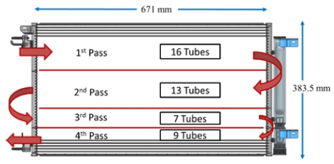
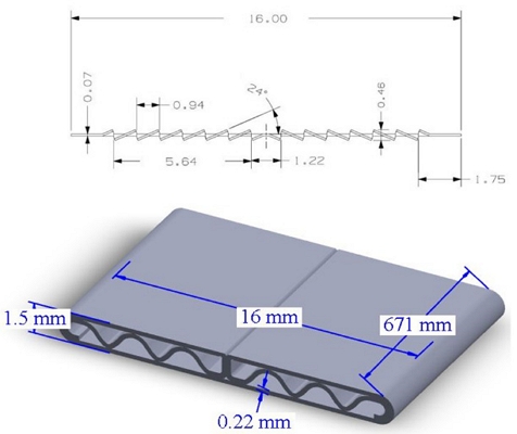
Fig. 1 shows the overall geometry of the microchannel condenser. It consists of 45 tubes divided into four passes, with 16 tubes in the first pass, 13 in the second, seven in the third, and nine in the fourth. Fig. 2 shows the fin and tube configuration made of aluminum. The tubes are 671 mm long with a hydraulic diameter of 0.89 mm, arranged in a single depth row. Louver fins were used, having a fin pitch of 2.5 mm. Detailed geometric specifications of the flat tube and louvered fin are provided in Table 1. R134a was used as a refrigerant in this study.
2.2 Operating conditions
As the given geometry consists of a single slab, air inlet conditions for each tube remain the same in all passes. The dry-bulb temperature, wet-bulb temperature, atmospheric pressure, and airflow rate at each tube segment of the frontal row serve as the inputs for the air side. The refrigerant mass flow rate, along with the inlet pressure and temperature, are the input parameters for the refrigerant side of the heat exchanger's first tube. The output for the tube includes the refrigerant and air exit parameters together with the heating capacity and pressure drop.
The operating conditions listed in Table 2 are used to initialize the MATLAB code for the MCHE condenser. The air-side inlet temperature varies from 30 to 50℃, while the face velocity varies from 2 to 3 m/s. The refrigerant inlet's temperature varies between 95 and 115 degrees Celsius. All operating conditions are chosen within the practical range of mobile air-conditioning systems.
2.3 Heat transfer and pressure drop correlations
The convective heat transfer coefficient of the air-side is selected based on the fin configuration. In the present model, Kim and Bullard's16) Colburn j factor and friction f factor for the louver fins are selected. Similarly, refrigerant-side heat transfer coefficients and friction factors are selected based on the flow regimes. A well-known Gnielinski's correlation17) is used for single-phase turbulent flow. The latest Shah18) correlation for mini/microchannel heat exchangers is utilized for two-phase condensation.
2.4 Numerical methodology
A segment-by-segment modeling approach, as used by Kim and Bullard19), is utilized to model MCHE, in which each segment is treated as a small crossflow heat exchanger, and the heat transfer and pressure drop equations are solved for each segment individually.
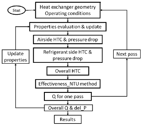
Each pass consists of a different number of tubes with similar flow conditions. Therefore, one tube was divided into five segments along the refrigerant flow direction. The model is based on the effectiveness-NTU method to calculate each segment's heat transfer and pressure drop. Once first segment's heat transfer and pressure drop are calculated, it is repeated for the following segments of the same tube. The outlets of one segment are considered an inlet for the next segment, and the same procedure is repeated until the last segment of the last pass. The total heat exchanger capacity is the summation of the individual performance of all tubes. Similarly, the pressure drop across each pass is the average of the pressure drops along each tube in the respective pass.
The following assumptions are made in developing the model to simplify the numerical task.
- • A uniform refrigerant flow rate is considered in each tube.
- • Refrigerant is either in a single- or two-phase region in each segment.
For each tube segment, the energy balance equations are used to calculate the heat transfer between the refrigerant and the air. The ε-NTU method for crossflow configuration with one fluid mixed and the other fluid unmixed is used for this purpose (Kays and London, 1984). The refrigerant is modeled as a mixed fluid, and the air is modeled as an unmixed fluid. UA is an overall thermal conductance which is calculated using Eq. (1),
| (1) |
Air and refrigerant side heat transfer coefficients are calculated using correlations provided in section 2.3. The heat exchange effectiveness, ε, is the ratio of the change in temperature, ΔT, to the maximum possible temperature change, based on the inlet temperatures of the two fluids. ε is calculated for each segment depending on each fluid's heat capacity, C.
For the case in which Cmax = Cunmixed (in other words, when the air has the higher heat capacity) Eqs. (2a) and (2b) are used,
| (2a) |
| (2b) |
On the other hand, for Cmax = Cmixed, ε is calculated for each segment using Eqs. (3a) and (3b).
| (3a) |
| (3b) |
When the refrigerant in a tube is in the two-phase regime Eqs. (4a) and (4b) are utilized,
| (4a) |
| (4b) |
Once ε is calculated for the segment, the outlet temperature of either the air-side or the refrigerantside can be calculated followed by the heat load. The stepwise numerical methodology is summarized in Fig. 3.
3. Model verification
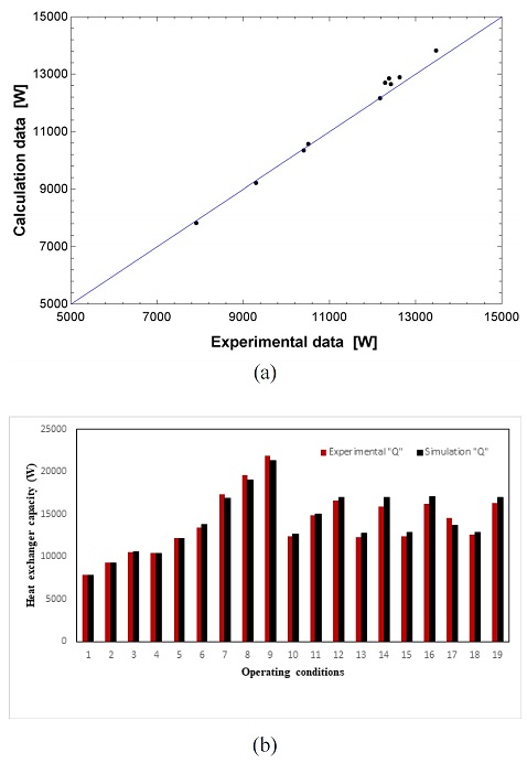
The model verification was performed using experimental data collected over a wide range of operating conditions. Sections 2.1 and 2.2 show the condenser configuration and operating conditions, respectively.
The performance results of the simulation code against the available experimental data for the refrigerant R134a MCHE model are presented in Fig. 4. Comparisons were performed at fifteen different operating conditions. The comparison results showed an average difference of 1.86% based on the heat exchanger capacity.
4. Conclusion
An extensive MATLAB code for analyzing MCHEs was established and validated for folded tube MCHEs. A segment-by-segment modeling approach was used to evaluate thermo-hydraulic performance. It is applicable to various microchannel configurations used as a condenser for various operating conditions, provided that the face airflow velocity and refrigerant inlet conditions are known. For each flow regime, state-of-the-art heat transfer and pressure drop correlations were used. The model developed in the study accurately predicted the experimental data and can be used for performance analysis and design of a microchannel condenser with minimal numerical uncertainty. However, more research is needed to fully understand the refrigerant-side pressure drop behavior.
Nomenclature
| Ao : | total air-side surface area, m2 |
| Ai : | internal tube surface area, m2 |
| Am : | mean tube surface area, m2 |
| C : | heat capacities, J/K |
| Fd : | flow depth, mm |
| hr : | refrigerant side HTC, W/m2 K |
| ha : | airside HTC, W/m2 K |
| Kt : | thermal conductivity, W/mK |
| La : | louver angle, deg. |
| Lp : | louver pitch, mm |
| mr : | refrigerant mass flowrate, kg/min |
| T : | temperature, K |
| P : | pressure, kPa |
| v : | velocity, m/s |
| UAo : | overall heat transfer coefficient, W/K |
Greek letters
| δt : | tube wall thickness, m |
| ƞo : | surface effectiveness |
| ε : | effectiveness |
Subscript
| air : | air |
| ref : | refrigerant |
| in : | inlet |
| out : | outlet |
Abbreviations
| HVAC : | heating, ventilation, and air conditioning |
| HTC : | heat transfer coefficient |
| MCHE : | microchannel heat exchanger |
| NTU : | number of transfer units |
| VOF : | volume of fluid |
Acknowledgments
This work was partly supported by Korea Evaluation Institute of Industrial Technology (KEIT) grant funded by the Korea government (MOTIE) (Project No. 20015917).
References
-
S. G. Kandlikar, S. Colin, Y. Peles, S. Garimella, R.F. Pease, J. J. Brandner, and D. B. Tuckerman, “Heat transfer in microchannels-2012 status and research needs”, J. Heat Transfer, Vol. 135, No. 9, 2013, pp. 091001.
[https://doi.org/10.1115/1.4024354]

-
M. H. Kim and C. W. Bullard, “Performance evaluation of a window room air conditioner with microchannel condensers”, J. Energy Resour. Technol., Vol. 124, No. 1, 2002, pp. 47-55.
[https://doi.org/10.1115/1.1446072]

-
J. C. S. Garcia, H. Tanaka, N. Giannetti, Y. Sei, K. Saito, M. Houfuku, and R. Takafuji, “Multiobjective geometry optimization of microchannel heat exchanger using real-coded genetic algorithm”, Appl. Therm. Eng., Vol. 202, 2022, pp. 117821.
[https://doi.org/10.1016/j.applthermaleng.2021.117821]

-
C. H. Kim, H. S. Kim, H. S. Lim, J. W. Choi, I. H. Choi, and N. H. Kim, “Two-phase refrigerant distribution for a horizontal header/horizontal mini-channel tube configuration”, Heat Mass Transf., Vol. 58, 2022, pp. 587-600.
[https://doi.org/10.1007/s00231-021-03135-5]

-
A. Saleem and M. H. Kim, “Air-side thermal hydraulic performance of microchannel heat exchangers with different fin configurations”, Appl. Therm. Eng., Vol. 125, 2017, pp. 780-789.
[https://doi.org/10.1016/j.applthermaleng.2017.07.082]

-
H. Lim, U. Han, and H. Lee, “Design optimization of bare tube heat exchanger for the application to mobile air conditioning systems”, Appl. Therm. Eng., Vol. 165, 2020, pp. 114609.
[https://doi.org/10.1016/j.applthermaleng.2019.114609]

- Z. Li, J. Ling, V. Aute, and R. Radermacher, “Investigation of port level refrigerant flow maldistribution in microchannel heat exchanger”, 12th IEA Heat Pump Conference, 2017, pp. 1-11. Retrieved from http://hpc2017.org/wp-content/uploads/2017/05/O.3.1.4-Investigation-of-Port-Level-Flow-Maldistribution-in-Microchannel-Heat-Exchanger.pdf, .
-
E. Da Riva and D. Del Col, “Effect of gravity during condensation of R134a in a circular minichannel : VOF simulation of annular condensation”, Microgravity Sci. Techn., Vol. 23, No. Suppl 1, 2011, pp. 87-97.
[https://doi.org/10.1007/s12217-011-9275-4]

-
E. Da Riva and D. Del Col, “Numerical simulation of laminar liquid film condensation in a horizontal circular minichannel”, J. Heat Transfer, Vol. 134, No. 5, 2012, pp. 051019.
[https://doi.org/10.1115/1.4005710]

-
H. Ganapathy, A. Shooshtari, K. Choo, S. Dessiatoun, M. Alshehhi, and M. Ohadi, “Volume of fluid-based numerical modeling of condensation heat transfer and fluid flow characteristics in microchannels”, Int. J. Heat and Mass Transfer, Vol. 65, 2013, pp. 62-72.
[https://doi.org/10.1016/j.ijheatmasstransfer.2013.05.044]

-
S. Bortolin, E. Da Riva, and D. Del Col, “Condensation in a square minichannel: application of the VOF method”, Heat Transfer Eng., Vol. 35, No. 2, 2014, pp. 193-203.
[https://doi.org/10.1080/01457632.2013.812493]

-
P. Gunnasegaran, H. A. Mohammed, N. H. Shuaib, and R. Saidur, “The effect of geometrical parameters on heat transfer characteristics of microchannels heat sink with different shapes”, International Communications in Heat and Mass Transfer, Vol. 37, No. 8, 2010, pp. 1078-1086.
[https://doi.org/10.1016/j.icheatmasstransfer.2010.06.014]

-
H. Wang, Z. Chen, and J. Gao, “Influence of geometric parameters on flow and heat transfer performance of micro-channel heat sinks”, Applied Thermal Engineering, Vol. 107, 2016, pp. 870-879.
[https://doi.org/10.1016/j.applthermaleng.2016.07.039]

-
Y. Chen, C. Zhang, M. Shi, and J. Wu, “Three-dimensional numerical simulation of heat and fluid flow in noncircular microchannel heat sinks”, International Communications in Heat and Mass Transfer, Vol. 36, No. 9, 2009, pp. 917-920.
[https://doi.org/10.1016/j.icheatmasstransfer.2009.06.004]

-
D. Jing and L. He, “Numerical studies on the hydraulic and thermal performances of microchannels with different cross-sectional shapes”, International Journal of Heat and Mass Transfer, Vol. 143, 2019, pp. 118604.
[https://doi.org/10.1016/j.ijheatmasstransfer.2019.118604]

-
M. H. Kim and C. W. Bullard, “Air-side thermal hydraulic performance of multi-louvered fin aluminum heat exchangers”, International Journal of Refrigeration, Vol. 25, No. 3, 2002, pp. 390-400.
[https://doi.org/10.1016/S0140-7007(01)00025-1]

-
M. H. Kim, S. Y. Lee, S. S. Mehendale, and R. L. Webb, “Microchannel heat exchanger design for evaporator and condenser applications”, Advances in Heat Transfer, Vol. 37, 2003, pp. 297-429.
[https://doi.org/10.1016/S0065-2717(03)37004-2]

-
M.V M. Shah, “Improved correlation for heat transfer during condensation in conventional and mini/micro channels”, International Journal of Refrigeration, Vol. 98, 2019, pp. 222-237.
[https://doi.org/10.1016/j.ijrefrig.2018.07.037]

-
M. H. Kim and C. W. Bullard, “Development of a microchannel evaporator model for a CO2 air conditioning system”, Energy, Vol. 26, No. 10, 2001, pp. 931-948.
[https://doi.org/10.1016/S0360-5442(01)00042-1]


