R410A 대체냉매 R32와 R454B의 미세핀 관내 응축 열전달
2022 The Korean Hydrogen and New Energy Society. All rights reserved.
Abstract
This paper presents two-phase condensation heat transfer and pressure drop characteristics of R32 and R454B as an alternative refrigerant to R410A in a 9.52 mm OD microfin tube. The test facility has a straight, horizontal test section with an active length of 2.0 m and is cooled by cold water circulated in a surrounding annular space. The heat transfer coefficients of the annular space were obtained using the modified Wilson plot method. Average condensation heat transfer coefficient and pressure drop data are presented at the condensation temperature of 35℃ for the range of mass flux 100-400 kg/m2s. The average condensation heat transfer coefficients of R32 refrigerant are 35-47% higher than R410A at the mass flux considered in the study, while R454B data are similar to R410A. The average pressure drop of R32 and R454B are much higher than R410A and they are 134-224% and 151-215% of R410A, respectively. R32 and R454B have relatively low GWP and high heat transfer characteristics, so they are suitable as alternatives for R410A.
Keywords:
Condensation Heat transfer, Mirofin tube, Alternative refrigerant, R32, R454B, R410A키워드:
응축열전달, 미세핀관, 대체냉매1. 서 론
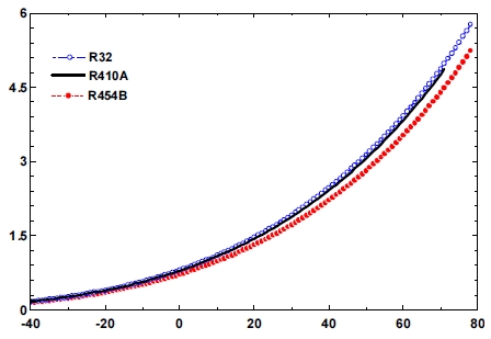
산업의 고도화와 생활 수준의 향상으로 냉동공조장치의 사용이 지속적으로 증가하고 있으며, 이에 따른 에너지 수급과 환경문제가 중요한 이슈로 부각 되고 있다. 냉동공조 시스템이 환경에 미치는 영향은 시스템에 사용되는 냉매와 시스템 운전 시 소요되는 전력 소비에 따른 지구온난화 효과를 모두 고려해야 한다1). 따라서 오존층파괴지수(ozone depletion potential, ODP)가 0이고 지구온난화지수(global warming potential, GWP)가 작은 친환경 대체냉매의 사용과 시스템의 에너지 효율을 증대시키는 것은 매우 중요하다1,2). 가정용 에어컨에 많이 사용되고 있는 R410A 냉매는 ODP는 0이나 GWP가 2,088로 상대적으로 높다. 따라서 국내외에서 R410A의 대체냉매로 GWP가 낮은 R32와 R454B 등을 적용하기 위한 많은 연구가 진행되고 있다3,4). Table 1에 R32와 R454B의 일반적 특성을 R410A와 비교하여 나타내었는데, R32와 R454B 냉매는 GWP가 각각 675와 466으로 낮은 반면 가연성 등급이 A2L로 R410A보다 높다5,6). 그리고 R454B의 포화온도 35℃에서의 온도글라이드도 1.0℃로 R410A의 0.1℃보다 상대적으로높다. Fig. 1에는 R410A와 대체냉매의 증기압곡선을 도시하였는데, 포화증기압 특성이 서로 유사한 것을 관찰할 수 있다. 이러한 특성을 반영한 시스템과 열교환기와 같은 구성 부품의 설계를 위해서는 시스템의 운전조건에서의 관내 열전달계수를 정확하게 평가하는 것이 중요하다. 관내의 응축열전달 계수를 측정하기 위해서는 주어진 열교환기의 기하학적 형상에 대해 운전조건에 따른 작동유체의 온도와 전열관의 벽면 온도를 측정하여야 한다. 이로부터 뉴턴의 냉각법칙을 이용하여 응축열전달계수를 구할 수 있다. 그러나 열교환기의 전열관의 벽면 온도를 정확히 측정하는 것은 간단하지가 않다. 그 이유는 사용되는 관의 외경이 9.52 mm 이하의 소구경 전열관이 많이 사용되고 있으며 미세핀관의 경우 벽면의 두께가 매우 작으며7), 전열관 벽면의 온도가 위치에 따라 변하고 온도 측정 센서에 의해 유동이 교란될 수 있기 때문이다. 따라서 벽면 온도를 직접 측정하지 않고 관내의 응축열전달계수를 평가하기 위해 대수평균온도차(log mean temperature difference, LMTD)를 이용하는 방법을 사용한다. 이를 위해서는 환상유로의 대류열전달상관식이 필요하며, 관내의 응축열전달계수는 총괄열전달계수 표현식에서 환상유로와 관벽의 전도 열저항값을 제외하여 계산한다.
본고의 목적은 GWP가 작은 R410A의 대체냉매의 미세핀 관내의 평균 응축열전달과 압력강하 특성을 실헙적으로 평가하는 것이다. 응축열전달 실험은 외경 OD=9.52-mm, 길이 2.0 m의 수평 미세핀관을 사용하고 응축온도 35℃, 질량 유속 100-400 kg/m2-s에서 냉매 R410A, R32 및 R454B를 이용해 수행한다. 실험에서 구한 대체냉매의 평균 응축열전달계수와 압력강하 특성을 R410A와 비교한다.
2. 실 험
2.1 실험장치
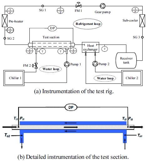
본 연구에서 사용된 실험장치의 개략도와 전열관의 형상을 Figs. 2, 3에 각각 나타내었다. 실험장치는 크게 냉매와 열전달 유체의 순환 루프로 구성되며, 시험부는 길이가 2 m인 동심이중원관으로 구성되는데, 실험장치의 상세한 구조, 자료 취득장치 및 운전 방법 등은 참고문헌에 잘 기술되어 있다7-10). 시험부의 전열관은 Fin 높이 h=0.25 mm인 60개의 산으로 구성되며, 산각 γ=30°, 나선각 φ=15-30°, 관의 내경과 외경은 각각 ID=8.92 mm와 OD=9.52 mm이다. 시험부의 냉매측과 물측의 입/출구 온도는 RTD 센서(PT100Ω)로 측정하고, 유량은 질량유량계를 사용하여 측정한다. 시험부 관내의 냉매의 입/출구의 압력과 차압도 압력센서와 차압센서를 이용해 동시에 측정한다.

Schematic of the experimental facility. T/P, temperature and pressure sensors; FM, flow meter, DP, differential pressure sensor; and SG, sight glass.
2.2 실험조건 및 방법
본 연구에서의 실험조건을 Table 2에 나타내었다. 모든 실험은 응축온도 35℃에서 질량 유속을 100-400 kg/m2-s 변화시키면서 진행한다. 실험냉매는 R410A, R32 및 R454B이며 시험부 입구의 과열도와 출구의 과냉도는 각각 5℃와 2℃로 유지한다. 냉매의 질량유량은 마그네틱 기어펌프의 입력 전력을 조절하여 제어한다. 시험장치의 제한성으로 냉매의 건도 변화에 따른 국소열전달 특성을 측정할 수 없으므로 평균 응축열전달계수와 압력강하를 측정하고 비교한다. 실험조건과 수집할 자료는 PC에서 온라인으로 모니터링을 하고, 운전상태가 정상상태가 되면 10분간의 자료를 평균하여 기록한다. 응축열전달 실험에 앞서 물대물 실험을 질량유량 200-800 kg/hour 범위에서 100 kg/hour씩 증가시키면서 수행하여 환상공간의 열전달계수를 Wilson plot 방법으로 구한다11,12).
2.3 실험자료 처리
본 연구에서와 같이(Fig. 2) 대향류방식으로 열교환이 이루어지는 시험부에서의 총괄열전달계수(UoAo)는 다음 식으로 표현된다.
| (1) |
| (2) |
여기서 Q는 시험부에서의 열전달량으로 환상유로의 물측의 열량(Qo)과 관내측 냉매의 열전달량(Qi)의 산술평균이며, 다음 식으로 구한다.
| (3) |
| (4) |
| (5) |
여기서, mo 와 mi 는 각각 냉각수와 냉매의 질량유량이고 To1, To2 및 ei1, ei2 는 각각 시험부 입/출구의 냉각수의 온도와 냉매측의 엔탈피이다. 그리고 LMTD는 대수평균온도차로 다음과 같다.
| (6) |
식 (1)에서 첫째항과 셋째항은 각각 환상유로와 관내유로의 대류 열저항이고, Rw는 관벽에서의 전도열저항이다. 본 연구에서는 전열관이 구리이고 관 두께가 매우 작아서 전도 열저항은 무시하였다.
환상공간의 열전달계수를 알면 식 (1)에서 관내의 냉매의 응축열전달계수를 구할 수 있다. 냉매의 물성치는 NIST REFPROP 105)을 사용하였다. Table 3에는 오차해석을 나타내었는데, 실험에 사용된 모든 센서의 오차를 평균 열전달계수와 압력강하는 각각 ±3.5-10.7%와 ±1.5-8.2%로 나타났다13).
3. 결과 및 고찰
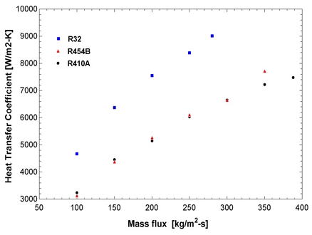
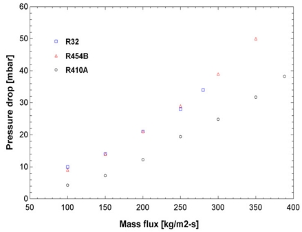
Figs. 4, 5에 평균 응축 열전달계수와 압력강하 특성을 응축온도 35℃, 질량 유속 100-400 kg/m2s에 대해 각각 나타내었다. 모든 냉매의 응축 열전달계수는 질량 유속에 따라 증가하는 경향을 보이고 있으며, R32의 경우는 모든 질량 유속 범위에서 R410A에 비하여 35-47% 높은 비율의 응축 열전달계수를 보이고 있는데, 질량 유속이 작은 부분에서의 열전달계수의 비율 차이가 더 크게 나타났다. 이는 Table 4에서 보인 바와 같이 R32의 정압비열과 열전도계수의 값이 상대적으로 높은 데 일부 기인한다고 볼 수 있다. R454B의 경우 질량 유속이 300 kg/m2s보다 작은 범위에서는 R410A와 유사한 경향을 나타내고 질량 유속이 더 증가하면 R410A보다 높은 값을 보이는 것을 알 수 있다.
압력강하는 R32와 R454B의 경우가 R410A에 비하여 상대적으로 높게 나타났는데, 이는 Table 4에서 볼 수 있듯이 이들 냉매의 밀도가 R410A 냉매에 비해 작아서 같은 질량 유속의 경우 냉매의 유속이 크기 때문일 것으로 보인다. 실제로 R32와 R454B의 냉매의 평균 압력강하량은 R410A에 비하여 각각 35-124% 및 51-115% 높은 비율로 나타났으며, 질량 유속이 작은 경우가 압력강하의 비율 차이가 크게 나타났다.
4. 결 론
R410A 냉매의 대체냉매 R32와 R454B에 대한 외경 9.52 mm의 미세핀 관내 응축 열전달 특성 실험을 수행하여 다음과 같은 결론을 얻었다.
1) R32의 평균 응축열전달계수는 R410A에 비하여 응축온도 35℃, 질량 유속 100-400 kg/m2s에서 35-47% 높으며, 질량 유속이 증가할수록 그 차이는 감소한다.
2) R454B의 평균 응축열전달계수는 R410A의 96-106% 수준으로 큰 차이가 없으며, 저 질량 유속에서는 R410A보다 작다가 질량 유속이 증가하면서 R410A보다 커진다.
3) 평균 압력강하의 경우 R32와 R454B 냉매는 R410A에 비하여 각각 35-124% 및 51-115% 높으며, 질량 유속이 작은 경우 압력강하의 차이가 더 크다.
4) 단일 냉매인 R32는 포화 증기압-온도 특성 및 열전달 측면에서 R410A의 대체냉매로 적합하며 성능이 우수할 것으로 보인다. R454B 혼합냉매도 응축온도 35℃에서 온도 글라이드가 1.0 정도로 R410A보다 크지만, drop-in 대체냉매로 사용할 수 있다.
5) 대체냉매 열교환기의 설계를 위해서는 건도에 따른 국소 이상유동 열전달 특성과 상관식도 필요하므로 이에 대한 추가 연구가 요구된다.
Nomenclature
| DP : | differential pressure sensor |
| GWP : | global warming potential |
| HFC : | hydrofluoro-carbon |
| HFO : | hydofluoro-olefin |
| ID : | inner diameter |
| FM : | flow meter |
| LMTD : | log mean temperature difference |
| NBP : | normal boiling point |
| OD : | outer diameter |
| ODP : | ozone depletion potential |
| PC : | personal computer |
| SG : | sight glass |
| A : | area (m2) |
| cp : | specific heat (J/kg-K) |
| e : | enthalpy (J/kg) |
| h : | heat transfer coefficient (W/m2-K) or fin height (mm) |
| M : | mass flow meter |
| m : | mass flow rate (kg/h) |
| P : | pressure (kPa) |
| ΔP : | pressure drop (mbar) |
| qv : | volumetric capacity (kJ/m3) |
| Q : | heat transfer rate (W) |
| Rw : | thermal conduct resistance (K/W) |
| S : | specific entropy (J/kg-K) |
| T : | temperature (℃) |
| tb : | bottom wall thickness (mm) |
| U : | overall heat transfer coefficient (W/m2-K) |
| γ : | apex angle (°) |
| ψ : | helix angle (°) |
Subscripts
| 1 : | inlet |
| 2 : | outlet |
| c : | critical |
| i : | tube-side |
| o : | annular-side |
References
-
G. Blanco, R. Gerlagh, and S. Suh. “Drivers, trends and mitigation”, Climate Change 2014, Cambridge University Press, UK, 2014, pp. 351–412. Retrieved from https://www.ipcc.ch/site/assets/uploads/2018/02/ipcc_wg3_ar5_chapter5.pdf, .
[https://doi.org/10.1017/CBO9781107415416.011]

-
M. H. Kim, J. Pettersen, and C. W. Bullard, “Fundamental process and system design issues in CO2 vapor compression systems”, Progress in Energy and Combustion Science, Vol. 30, No. 2, 2004, pp. 119-174.
[https://doi.org/10.1016/j.pecs.2003.09.002]

-
V. H. Panato, D. F. M. Pico, and E. P. B. Filho, “Experimental evaluation of R32, R452B and R454B as alternative refrigerants for R410A in a refrigeration system”, Int. J. Refrig., Vol. 135, 2022, pp. 221-230.
[https://doi.org/10.1016/j.ijrefrig.2021.12.003]

- R. Yıldırım, A. Güngör, K. Kumaş, and A. Akyüz, “Evaluation of low GWP refrigerants R452B and R454B as alternative to R410a in the heat hump systems”, J. Int. Environmental Application & Science, Vol. 16, No. 2, 2021, pp. 47-52. Retrieved from https://dergipark.org.tr/en/download/article-file/1806332, .
-
E. W. Lemmon, I. H. Bell, M. L. Huber, M. O. McLinden, “NIST standard reference database 23: reference fluid thermodynamic and transport properties-REFPROP, version 10.0”, National Institute of Standards and Technology, Standard Reference Data Program, Gaithersburg, 2018.
[https://doi.org/10.18434/T4/1502528]

- ANSI/ASHRAE, “ANSI/ASHRAE standard 34-2013: designation and safety classification of refrigerants”, ASHRAE Standard, 2013.
-
M. H. Kim, “Heat transfer coefficients of concentric annuli for testing heat transfer characteristics of alternative refrigerants in tubes”, Trans Korean Hydrogen New Energy Soc, Vol. 32, No. 1, 2021, pp. 63-67.
[https://doi.org/10.7316/KHNES.2021.32.1.63]

-
A. Karageorgis, G. Hinopoulos, and M. H. Kim, “A comparative study on the condensation heat transfer of R-513A as an alternative to R-134a”, Machines, Vol. 9, No. 6, 2021, pp. 114.
[https://doi.org/10.3390/machines9060114]

-
M. H. Kim and J. S. Shin, “Condensation heat transfer of R22 and R410A in horizontal smooth and microfin tubes”, Int. J. Refrig., Vol. 28, No. 6, 2005, pp. 949-957.
[https://doi.org/10.1016/j.ijrefrig.2005.01.017]

-
M. H. Kim and J. S. Shin, “Evaporating heat transfer of R22 and R410A in horizontal smooth and microfin tubes”, Int. J. Refrig., Vol. 28, No. 6, 2005, pp. 940-948.
[https://doi.org/10.1016/j.ijrefrig.2005.01.016]

- E. E. Wilson, “A basis for rational design of heat transfer apparatus”, ASME Trans., Vol. 37, 1915, pp. 47-82.
- D. E. Briggs and E. H. Young, “Modified Wilson plot techniques for obtaining heat transfer correlations for shell and tube heat exchangers”, ASME Trans. J. of Heat Transfer, Vol. 5, 1969, pp. 51-56.
-
R. J. Moffat, “Describing the uncertainties in experimental results”, Exp. Therm. Fluid Sci., Vol. 1, No. 1, 1998, pp. 3-17.
[https://doi.org/10.1016/0894-1777(88)90043-X]


