정량적 위험성평가 프로그램(Hy-KoRAM)을 이용한 제조식 수소충전소 피해범위 및 영향 분석
2020 The Korean Hydrogen and New Energy Society. All rights reserved.
Abstract
As the hydrogen industry grows, expansion of infrastructure for hydrogen supply is required, but the safety of hydrogen facilities is concerned due to the recent accidents at the Gangneung hydrogen tank and the Norwegian hydrogen fueling station. In this study, the damage range and impact analysis on the on-site hydrogen fueling station was conducted using Hy-KoRAM. This is a domestically developed program that adds functions based on HyRAM. Through this risk assessment, it was evaluated whether the on-site hydrogen fueling station meets international standards and suggested ways to improve safety.
Keywords:
Hydrogen, On-site hydrogen fueling station, Damage range, Hazard distance, Risk assessment키워드:
수소, 제조식 수소충전소, 피해범위, 위험거리, 위험성평가1. 서 론
최근 정부의 수소경제 활성화 로드맵 발표(’19.1)와 함께 적극적인 정책 추진의 결과로 수소산업의 발전이 급속하게 이루어지고 있다. 수소에너지는 차세대 청정연료로서 수송·발전·건물·산업 등의 원료로 활용되고 있으며, 관련 인프라 확충과 기술개발로 인해 급격한 성장세를 보이고 있다. 특히, 1998년 국가 G7 사업 및 차세대 자동차 개발 사업을 기점으로 수소차 개발을 시작하여 교통 인프라 보급이 확대되고 있으며 2040년까지 수소차 290만 대, 수소충전소 1,200개소를 목표로 하고 있다. 이러한 수소차 보급 및 시장 활성화를 위해 수소충전소의 확대가 필요하나 이전까지 국내에서는 충전 인프라에 대한 신뢰성 있는 위험성평가 프로그램이 부재하였기 때문에 안전성 확인에 어려움이 있었다.
본 연구에서는 이를 위해 수소충전소 전용 위험성평가 프로그램인 Hy-KoRAM을 활용하여 제조식 수소충전소에 대한 정량적 위험성평가를 수행하였다.
수소충전소는 수소의 공급 방식에 따라 저장식과 제조식으로 나누어진다. 제조식 수소충전소는 수소의 원료가 되는 가스를 개질기와 같은 추출장치로 수소를 직접 생산하여 수소차에 공급하는 방식으로서 충전소 건설비용이 높아 국내에서는 주로 저장식 수소충전소 방식을 이용하고 있다. 하지만 수소충전차량의 수요가 점점 증가함에 따라 수소 공급 요구량이 증대되면서 여러 지역에서 제조식 수소충전소 설치사업을 확대 실시하고 있다. 따라서 본 연구를 통해 제조식 수소충전소에 대한 피해 범위 및 영향을 분석하여 안전성을 제고하고자 한다.
2. 위험성평가 프로그램(Hy-KoRAM)
본 연구는 제조식 수소충전시스템의 피해범위와 영향을 분석하기 위하여 정량적 위험성평가 프로그램인 Hy-KoRAM을 활용하였다. Hy-KoRAM은 가스 누출에 따른 피해 범위 예측 및 사고 빈도를 고려하는 프로그램으로서 department of energy (DOE)에서 개발한 HyRAM1,2)에 정성적·정량적 모듈을 보완하여 만든 위험성평가 프로그램이다. 현재, 국내에서는 Phast/Safeti, EFFECTS/RISKCURVES 등 주로 석유화학플랜트의 위험성을 평가하는 해외 범용 프로그램을 사용하고 있다. 하지만 해외 범용 프로그램은 국내환경 부합에 제한적이며 사용되는 고장률 데이터베이스에 따라 평가 결과의 편차가 크다.
따라서 본 연구에서는 최근 국내에서 국제공동연구를 통해 개발한 수소환경에 부합하는 위험성평가 프로그램인 Hy-KoRAM을 활용하여 제조식 수소충전소의 피해범위와 영향을 분석하고자 한다.
Hy-KoRAM은 수소충전소 사고 발생 시 피해반경을 기반으로 개인적 위험도 산출 및 주변 주민과 환경을 고려한 사회적 위험도(frequency-number curve) 산출이 가능하다. 또한, 수소 누출 및 제트화염 실증 시험을 기반으로 한 피해 영향 모델이 프로그램에 적용되었으며, 고장률데이터의 통계처리 방법을 이용해 수소설비에 적합하도록 failure frequency가 보정된다. Hy-KoRAM의 누출 제트 및 제트화염 모델 식은 HyRAM과의 산출방식과 동일하고 개인적위험도와 사회적위험도 산출 기능이 추가 되었으며 각각의 모델식은 아래와 같다1,3).
Jet release model equations
| (1) |
| (2) |
| (3) |
υ : velocity, ρ : density, cl : centerline, amb : ambient
B : characteristic half-width
λ : ratio of density spreading relative to velocity
r : perpendicular to the stream-wise direction
Y : mass fraction of hydrogen
Jet flame model equation
| (4) |
| (5) |
| (6) |
| (7) |
Srad : total emitted radiative power
C* : normalized radiative heat flux
Xrad : radiant fraction
: mass flow rate of fuel
∆Hc : heat of combustion (118.83 MJ/kg)
τf : flame residence time
fs : mass fraction of hydrogen in a stoichiometric mixture
ρf , Wf and Lvis : flame density, width and visible length
ρj , dj and uj : density, diameter and velocity of jet at exit
Individual risk
| (8) |
| (9) |
IRx,y : Total individual risk from death at geographic location “x,y”
IRx,y,i : Individual risk from death at geographic location “x,y” of accident case “i”
n : Total number of accident result cases considered in the analysis
fi : Frequency of accident case “i” in frequency analysis
Pf,i : Probability of accident case “i” causing death at location “x,y”
사회적 위험도를 산출하는 F-N 곡선을 계산하기 위한 과정은 개인적 위험도 산출 방식과 동일하며, 따라서 각 사고 결과 사례의 영향을 받는 사람의 수를 예측하기 위해서는 해당 정보를 인구 자료와 결합하여야 한다.
Societal risk
| (10) |
Ni : Number of deaths caused in accident case “i”
Px,y : Number of people at location “x,y”
3. 위험성평가 모델
3.1 제조식 수소충전소 개요
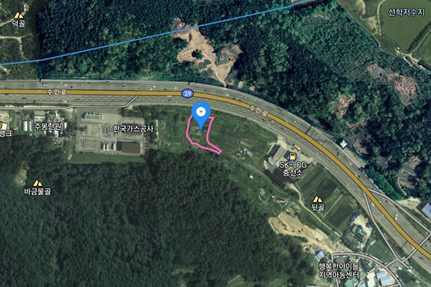
제조식 수소충전소의 정량적 위험성평가를 위해 수도권 근처에 위치한 제조식 수소충전소를 평가 모델로 선정하였다. 해당 충전소는 용기 또는 차량에 고정된 탱크에 고압가스를 충전할 수 있는 설비로 고압가스를 충전하는 것으로서 고압가스 제조(충전) 허가 대상에 포함된다. Table 1과 Fig. 1에 충전소의 위치 및 저장능력, 설계압력 등 시설사양을 표시하였으며, 수소충전소에서 사용되는 가스는 수소가스로써 처리량은 11,040 Nm3/day이다.
4. 위험성평가 조건
4.1 정량적 위험성평가 조건
피해영향평가를 통한 안전성평가 기준을 Table 2에 표시하였다.4) 수소가스 누출 시 4 kW/m2의 복사열이 방산될 경우 20초 내에 보호되지 않으면 통증과 함께 피부가 부풀어 오르고, 37.5 kW/m2의 복사열이 방산되면 장치 및 설비가 손상되는 정도의 영향을 미친다.5) 따라서 수소충전소 설치 시 Table 2에 명시한 기준들을 토대로 공정 설계 및 시설 기준을 이행하여 안전거리를 확보하여야 한다.
위험성평가 조건을 선정하기 위하여 누출원의 크기와 누출빈도에 대해 다음과 같이 기존의 문헌들을 참고하였다. 누출원의 크기는 IEC 60079-10-16) (KS C IEC 60079-10-17), KGS GC1018))에서 권장하는 2차 누출등급의 누출원 크기로 선정하였으며, 누출빈도는 SAND2009-0874 (2009)9)를 참조하였다.
특히 누출빈도의 경우 누출크기에 따라 보수적인 값을 반영하여 위험성평가를 수행하였으며 개질기·압축기(1차, 2차)·저장용기(LOW, MID, HIGH), 디스펜서에 대한 피해영향 결과를 도출하였다.
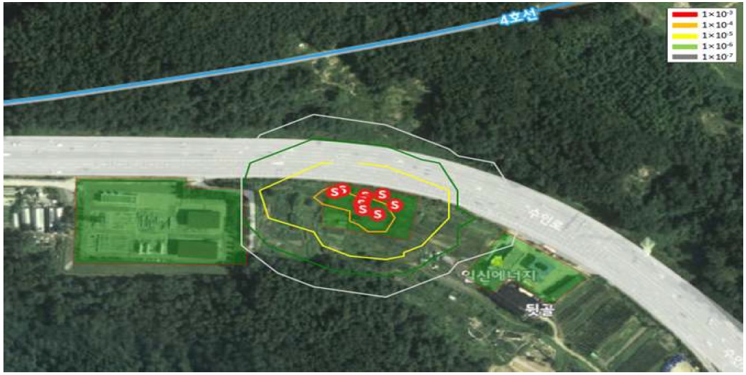
개인적/사회적 위험도 평가를 위한 인구분포는 주변지역 조사를 통해 다음과 같은 데이터를 사용하였다(Table 3).
5. 위험성평가 결과
5.1 ETA/HCA (flame, radiant heat) 해석 결과
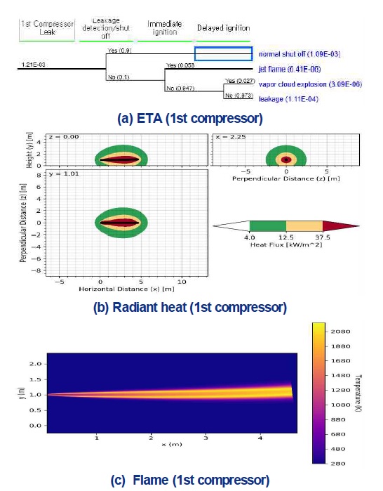
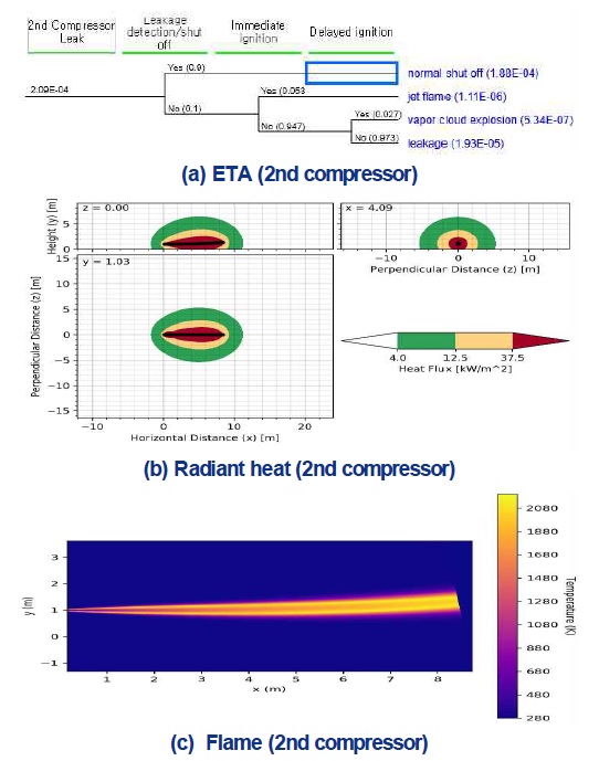
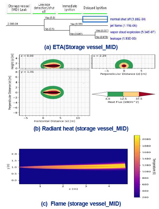
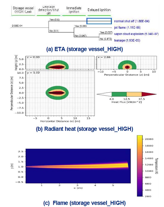
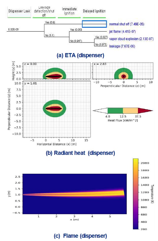
각 시설들의 위험성평가 조건에 따른 결과는 다음과 같다. Figs. 2-8에서 나타낸 ETA/ HCA 해석을 통해 화염길이와 복사열의 영향 범위를 확인할 수 있으며, ETA의 점화확률은 SAND 2012- 10150(2012)10)을 참조하여 분석하였다(Table 4).
ETA 분석 결과로부터 수소충전소의 가스 누출로 인해 발생 가능한 사고는 제트화재와 증기운 폭발임을 알 수 있고, 모든 시나리오에서 제트화재의 발생 가능성이 증기운 폭발보다 높게 나타나고 있다. 따라서 수소충전소의 안전거리 설정에 있어서 제트화재에 의한 피해범위가 주요 고려사항이라 할 수 있다.
제트화재 해석 결과 누출크기와 압력이 클수록 화염길이와 복사열이 미치는 영향이 크며, 특히 2차 압축기에서의 피해영향이 가장 큰 것으로 나타났다. 본 충전소 내에는 화기설비가 없어 화기와의 거리는 검토 대상에서 제외 되었으며, 사업소 경계와의 거리는 2차 압축기의 제트화재에 따른 복사열이 미치는 거리인 10.6 m 이상 확보가 필요하다. 본 시설은 사업소 경계와 15 m 이상의 이격거리를 확보하고 있고, 추가로 설비 주변에 방호벽을 설치하여 안전성을 강화하였다.
디스펜서로부터 발생한 제트화염의 피해범위는 7.5 m이고 본 시설은 디스펜서로부터 도로까지 23 m 이격거리를 확보하고 있어 안전성을 확보하고 있다. 설비간의 이격거리 검토에서는 현재 압축기와 압축가스설비가 방호벽 내의 공동 공간에 배치되어 있기 때문에 하나의 설비에서 사고 발생 시 다른 설비에 영향을 미칠 수 있다. 주변의 방호벽으로 인해 외부로의 영향은 차단이 가능하나 설비간 사고의 도미노 효과를 차단하기 위해서는 설비 사이의 격벽 설치를 통한 추가적인 안전조치가 필요할 것으로 보인다.
5.2 QRA 해석 결과
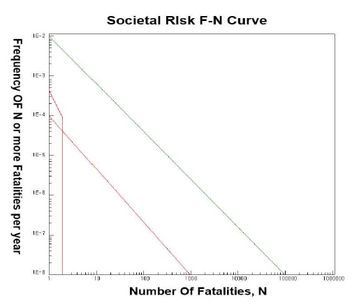
QRA 해석 결과를 분석하기 위해 위험도 허용 기준을 명시한 UK HSE11) 자료를 참조하였다(Table 5). 본 연구 대상인 제조식 수소충전소의 개인적 위험도(위험시설 주변에서 개인이 사상[死傷]할 수 있는 확률) 분석 결과, 작업자에 대한 허용 불가 영역(>1×10E-3) 및 작업장 밖에서의 일반 대중에 대한 허용 불가 영역(>1×10E-4)은 나타나지 않았으며, 충전소 주변의 인구현황 분포를 적용한 사회적 위험도 평가 결과 ALARP 영역(as low as reasonably practicable, 합리적으로 허용 가능한 범위) 및 완전 허용 가능 구역 내에 분포하는 것으로 확인되었다(Figs. 9, 10).
6. 결 론
본 연구는 제조식 수소충전소에 대해 국내에서 개발한 위험성 평가프로그램인 Hy-KoRAM을 이용하여 정량적 위험성평가를 수행하였다. 각 시설의 위험요인을 분석하기 위하여 국제표준(IEC 60079-10-1)에서 제시하고 있는 2차 누출 조건을 적용하였으며, 수소충전소 사고에 따른 피해 범위 및 영향을 확인하였다. 연구결과를 요약하면 다음과 같다.
1) 피해영향분석에서 2차 압축기의 피해영향이 가장 큰 것으로 나타났으며 압축기와 압축가스 설비가 방호벽 내의 공동 공간에 배치되어 있는 상태이기 때문에 한 설비에서 사고 발생 시 다른 설비로 사고가 전이 될 수 있어 격벽 등의 방호조치로 안전성을 강화하는 것이 권장된다.
2) 본 연구의 대상인 제조식 수소충전소의 개인적 위험도 분석 결과 작업자에 대한 허용 불가 영역(>1×10⁻³) 및 작업장 밖에서의 일반 대중에 대한 허용 불가 영역(>1×10⁻⁴)은 나타나지 않았으며, 충전소 주변의 인구현황 분포를 적용한 사회적 위험도 평가 결과 ALARP 영역 및 완전 허용 가능 구역 내에 분포하는 것으로 확인되었다.
Acknowledgments
본 연구는 산업통상자원부(MOTIE)와 한국에너지기술평가원(KETEP)의 지원을 받아 수행한 “수소충전소 위험성평가(risk assessment)를 위한 소프트웨어 개발” 연구과제입니다(20178520040490).
References
- K. M. Groth, E. S. Hecht, and J. T. Reynolds, “Methodology for assessing the safety of hydrogen systems: HyRAM 1.0 technical reference manual”, Sandia Report, SAND2015-10216, 2015.
-
B. W. Kang and T. H. Lee, “An investigation of hazard distance in a series of hydrogen jet fire with the hyram tools”, Trans. Korean Hydrogen New Energy Soc, Vol. 28, No. 2, 2017, pp. 166-173.
[https://doi.org/10.7316/KHNES.2017.28.2.166]

-
S. K. Kang, “A study of jet dispersion and jet-fire characteristics for safety distance of the hydrogen refueling station”, Journal of the Korean Institute of Gas, Vol. 23, No. 6, 2019, pp. 74-80.
[https://doi.org/10.7842/kigas.2019.23.6.74]

- “Review of 70MPa hydrogen station technical standards“, KHK, Japan, 2012.
- Kosha Guide P-102-2013, “Technical guide on accident damage prediction techniques”, Korea Occupational Safety and Health Agency, 2013. Retrieved from https://www.kosha.or.kr.
- IEC 60079-10-1, “Classification of areas-Explosive gas atmospheres”, International Electrotechnical Commission, 2015. Retrieved from https://www.iec.ch.
- KS C IEC 60079-10-1, “Classification of areas-explosive gas atmospheres”, Korean Standards Service Network, 2017.
- KGS GC 101, “Classification code for explosive hazardous area on gas facility”, Korea Gas Safety Corporation, 2018. Retrieved from https://cyber.kgs.or.kr/codesrc/kgscode_pdf/2018/GC101_180712.pdf.
- SAND2009-0874, “Analyses to support development of risk-informed separation distances for hydrogen codes and standards”, 2009. Retrieved from https://energy.sandia.gov/wp-content/uploads/2018/05/SAND2009-0874-Analyses-to-Support-Development-of-Risk-Informed-Separation-Distances-for-Hydrogen-Codes-and-Standards.pdf.
- SAND2012-10150, “Early-stage quantitative risk assessment to support development of codes and standard requirements for indoor fueling of hydrogen vehicles”, 2012.
- HID CI5A, “Guidance on ALARP decisions in COMAH, United Kingdom health and safety executive(UK HSE)”, 2019.

