13“ 비대칭 DPF 내 형상에 따른 배압 및 유동균일도 영향에 관한 전산해석연구
2020 The Korean Hydrogen and New Energy Society. All rights reserved.
Abstract
Recently, as the fine dust is increased and the emission regulations of diesel engines are strengthened, interest in diesel soot filtration devices is rapidly increased. In particular, there is a demand for technology development for higher efficiency of diesel exhaust gas after-treatment devices. As part of this, many studies conducted to increase the exhaust gas treatment efficiency by improving the flow uniformity of the exhaust gas in the DPF and reducing the pressure drop between the inlet and outlet of disel particle filter (DPF). In this study, computational fluid dynamics (CFD) simulation was performed when exhaust gas flows into the canning reduction device equipped with a 13” asymmetric DPF in order to maintain the flow uniformity in the diesel exhaust system and reduce the pressure. In particular, a study was conducted to find the geometry with the smallest pressure drop and the highest flow uniformity by simulating the DPF I/O ratio, exhaust gas temperature, inlet-outlet pressure and flow uniformity according to the geometry and hole size of distributor.
Keywords:
Computational fluid dynamics (CFD), Diesel, Exhaust gas, Exhaust pressure drop, Flow uniformity키워드:
전산유체해석, 디젤, 배기가스, 배압, 유동균일도1. 서 론
디젤엔진은 가솔린엔진에 비해 열효율과 출력이 좋아 대형차량의 엔진에 많이 사용되며 차량의 연료비 절감측면에서 디젤엔진을 선호하기도 한다. 그러나 디젤 연소 시 발생되는 배기가스는 CO, 질소산화물(NOx), 입자상물질(particle matters, PM)을 포함하고 있으며, PM 수도권 대기환경오염의 주범으로 꼽히고 있다. 이러한 환경문제들로 인해 디젤엔진을 대체하거나 디젤엔진에서 발생하는 오염물질을 저감할 수 있는 기술개발을 위해 노력하고 있다. 이러한 오염물질들은 NOx 물질은 디젤산화촉매(diesel oxidation catalyst, DOC), 선택적 환원 촉매(selective reduction catalyst), PM은 디젤매연여과장치(diesel particle filter, DPF) 기술을 적용함으로써 NOx와 PM을 저감할 수 있다1,2). DPF는 자동차 배출가스 중 PM 등을 촉매가 코팅된 필터로 여과한 후, 이를 산화시켜 이산화탄소와 수증기로 전환하여 오염물질을 제거한다. 디젤엔진차량은 DPF 부착의무를 가지며 현재 모노리스 타입의 세라믹 필터가 널리 쓰이고 있다. 그러나 세라믹 필터는 국부적인 열충격으로 인해 크랙이 발생할 수 있다. DPF는 PM이 산화하면서 발생할 수 있는 비정상적인 온도 상승이 일어나 내구성에 영향을 줄 수 있다. 또한 DOC는 열 충격에 의해 NOx 처리의 효율이 감소하고, 배기가스의 흐름이 균일하면 처리효율을 향상시킬 수 있기 때문에 배출가스 처리장치의 배기가스 유동균일도를 향상시켜 효율을 증대시킬 필요가 있다3).
또한 DPF는 입구와 출구채널이 교대로 막혀있는 구조적 특성상 배기가스 중에 포함된 입자상 물질들은 마이크로 크기의 기공들로 구성된 다공성 필터 벽을 통과하면서 여과된다4). 필터 내부에서 발생하는 몇 가지 물리적 메커니즘에 따라 입자상 물질 포집량이 증가하면 급격한 압력강하가 야기된다. 필터링이 진행되면서 필터 최상부의 기공들이 PM으로 메워지게 되면 더 이상 PM이 필터 내부로 침투할 수 없게 되고 필터 벽 상부면에는 PM층(soot cake)이 형성된다. 이러한 PM층은 스스로 필터 기능을 하게 되지만 PM층 높이가 증가하면 차압이 계속 증가하게 된다5).
이러한 필터 여과에 따른 압력강하 현상에 대해 수학적 모델 연구가 수행되어 왔으며, 최근 전산유체역학(computational fluid dynamics, CFD)을 이용하여 내부의 유동균일도, 압력, 온도분포 등 다양한 방법으로 연구에 적용하고 있다. Bissett6)의 연구에서 wall-flow 형태의 DPF에서 배기가스 유동 및 재생반응의 수학적 모델링 기초를 처음 확립하였고, Konstandipoulos 등7)에 의하여 가장 대표적으로 전산유체해석이 이루어졌다. 소프트웨어가 발달되면서 배기가스정화장치의 효율을 높이기 위한 최적화에 전산유체해석을 이용한 연구는 다양하게 진행되어 왔다8,9).
본 연구에서는 13”의 비대칭 DPF를 장착한 매연저감장치인 canning 내부에 배기가스가 유입될 때, 압력과 유동균일도를 fluent에 의한 CFD 시뮬레이션을 수행하였다. 특히 DPF I/O 비율, 배기가스 배출온도, 배기가스 입-출구 분배기의 형태 및 hole 크기 변경에 따른 입-출구 압력과 유동균일도에 대해 배압이 가장 작고 유동균일도가 높은 형상을 찾고자 연구를 수행하였다.
2. 시뮬레이션 해석 및 방법
2.1 지배방정식 및 경계조건
본 시뮬레이션에서 배기가스 저감장치의 해석은 전산유체역학 상용코드인 ANSYS Fluent 2020 R1을 이용하였다. 전산유체역학에서 사용되는 지배방정식은 정상상태 3차원 비압축성 유동(3-dimensional Reynolds averaged Navier-stokes)기반으로 배기가스의 난류 영향을 고려하기 위해 K-ℇ realized model을 이용하였다10). K-ℇ model은 대부분이 유체 흐름 문제에 널리 사용되는 방정식으로 realized model은 난류의 점도가 변수로 적용되는 소멸속도 ℇ에 대한 전달방정식이며 복잡한 구조의 흐름, 압력구배, 분리에 대해 예측이 가능하다. 온도분포를 위한 지배방정식으로 식 (1)의 연속방정식, 식 (2)의 모멘텀방정식, 식 (3)의 에너지방정식을 이용하였고, DPF와 DOC의 세라믹구조는 다공성 물질방정식(식 [4])을 통해 계산할 수 있다11).
| (1) |
| (2) |
| (3) |
| (4) |
여기서 p는 압력(Pa), υ는 유속(m/s), ρ는 유체밀도(kg/m3), 는 응력 텐서(stress tensor), Dij는 점성저항계수, Cij는 관성저항계수, (DOC는 3.5×10⁷, DPF는 2.6×10⁷), Cij=2β (DOC는 20.4, DPF는 0)이다.
2.2 유동균일도 해석방법
배기가스가 통과하는 촉매 표면에서의 유동균일도는 배기가스 저감장치의 정화효율과 수명에 많은 영향을 미치며, 일반적인 자동차의 배기계통은 배기가스가 정화장치의 입구부에 불규칙하게 유입되거나, 빠른 속도에 의해 DPF 촉매전면에 국부적으로 집중되는 현상이 나타난다. 촉매의 정화효율을 높은 상태로 유지하기 위해서 유동이 균일하게 촉매에 유입되어야 한다. 따라서 유동균일도는 촉매의 정화효율과 밀접한 관계가 있는 중요한 설계인자이다.
유동균일도의 경우 Weltense가 제안한 식을 이용하여 나타냈다.
여기서, wi는 local velocity, 는 평균유속을 나타낸다. 유동균일도가 1 (100%)이면 완전히 균일한 유동분포를 나타내며, 0 (0%)에 근접하면 극히 일부분에 유동이 집중됨을 의미한다. 일반적으로 배기가스 정화장치 설계에 있어서 0.9 (90%) 이상의 유동균일도가 요구된다12,13).
2.3 13“ DPF 저감장치 및 시뮬레이션
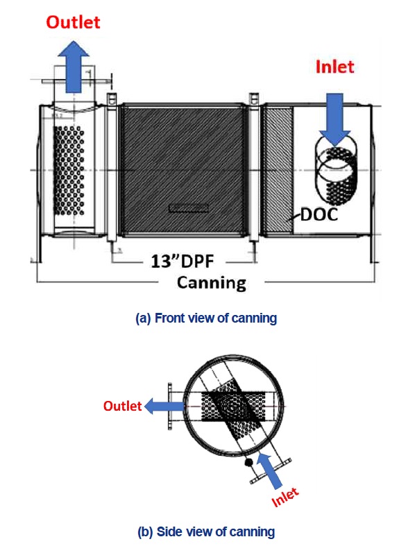
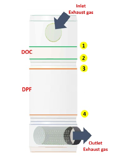
Fig. 1은 13“ DPF와 DOC가 장착된 canning 저감장치를 나타냈으며 이를 바탕으로 design modeler를 이용하여 모델링 하였다. 배기가스 조성은 Table 1과 같이 가정하여 fluid material을 air로 하였으며, Table 2와 같은 실제 배기가스 물성을 이용하여 시뮬레이션을 수행하였다. DPF 동시저감 장치의 입-출구의 지점에 대해서 Fig. 2의 DPF 장치 위치에서 배기가스의 유속, 온도와 DPF I/O ratio, canning 입-출구 distributor 형상, canning 입-출구 distributor hole 크기에 따른 배압 및 유동균일도를 계산하여 비교하였다.
3. 시뮬레이션 결과 및 고찰
3.1 DPF I/O ratio에 따른 압력 및 유동균일도
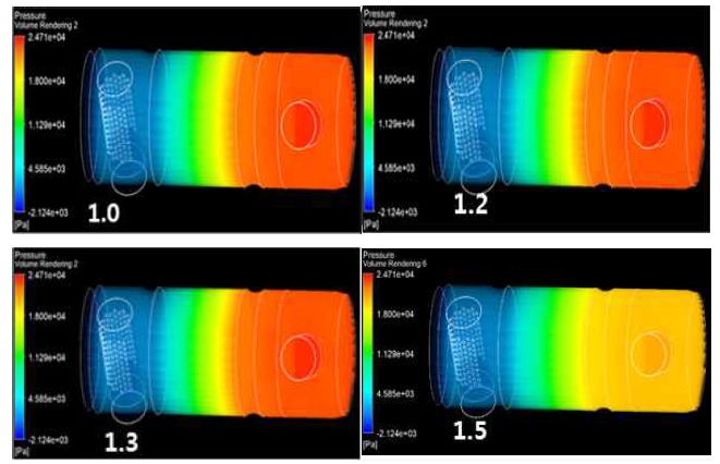
DPF 내에 배기가스 온도 310℃ (유속 49.7 m/s)에서 DPF I/O ratio가 증가함에 따른 시뮬레이션 결과를 Fig. 3과 Table 3에 나타냈다. Fig. 3에서 보듯이 DPF I/O ratio가 증가하면서 내부의 압력이 출구방향으로 가면서 더 낮아지는 것을 나타내고 있으며, 압력과 유동균일도를 Table 4에 수치화 하였다. 비등방성 DPF 배압은 등방성에 비해 약 16-26 mbar 감소하였으며, 유동균일도는 큰 차이가 없이 DPF는 약 98%, DOC는 약 93%로 일정하게 나타났다.
3.2 배출가스 온도에 따른 압력 및 유동균일도
DPF I/O ratio 1.2에서 배기가스 유속을 25℃ (25 m/s) 310℃ (49.7 m/s)로 시뮬레이션 한 입-출구의 압력 결과를 Fig. 4와 Table 5에 나타냈다. 온도가 증가하면 유속이 증가하게 되고 저감장치 내 압력이 증가하게 된다. 배압차이도 25℃보다 310℃에서 약 2배 크게 나타났다. 입출구의 유동균일도는 Table 6에서 보듯이 DPF에서의 98-99%로 매우 양호한 값을 나타내고 있다. 따라서 온도가 높은 배기가스에서도 유동균일도를 양호하게 유지하여 저감장치 효율을 유지할 수 있을 것으로 사료된다.
3.3 DPF Canning의 입구 형상에 따른 압력 및 유동균일도 해석
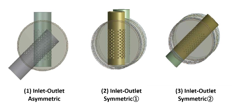
배기가스 유속 49.7 m/s에서 Fig. 5와 같이 DPF Canning의 입-출구를 1) 입구와 출구가 비대칭인 형상, 2) 출구 distributor 입구 distributor를 평행하게 한 형상, 3) 입구 distributor에 출구 distributor를 평행하게 한 형상으로 변경하여 시뮬레이션 한 압력과 유동균일도 결과를 Tables 7, 8에 나타냈다. Table에서 보듯이 세 가지의 형상에서 배압차이는 약 167-168 mbar로 차이가 거의 없었으며 유동균일도 역시 약 98%의 값으로 일정하게 나타났다.
3.4 Canning 입-출구 distributor의 hole 크기에 따른 압력 및 유동균일도 해석
배기가스 유속 49.7 m/s에서 DPF canning 입-출구 distributor hole 크기에 따른 입-출구의 압력을 시뮬레이션 한 결과를 Fig. 6과 Table 9에 나타냈다. Hole 크기가 10 mm에서 12.5, 15 mm로 증가할수록 압력은 감소한다. 가스가 입구 distributor에서 빠져나갈 때 hole의 크기가 커지면서 유속이 10 mm일 때보다 감소하게 되며, 배압이 감소한다. hole 크기를 1.5배로 증가시킨 15 mm와 10 mm의 배압 차이는 약 28 mbar로 나타났다. 또한 입-출구의 유동균일도는 Table 10에서 보는 바와 같이 hole 크기가 커질수록 DPF 내 유동균일도는 21% 이상 감소하는 것으로 나타났다. Hole 크기가 커지면 압력강하와 최대 유속이 작아지고, 작은 hole 사이즈일수록 유동저항이 증가하여 배압이 증가하게 된다14). 또한 hole 개수가 감소하면서 하나의 hole에서 빠져나가는 양이 작은 사이즈보다 증가하게 되면서 유동균일도는 감소하게 되는 것으로 사료된다.
4. 결 론
비등방성 DPF 설계의 최적화를 위해 CFD를 이용하여 DPF I/O ratio, 배기가스 온도, canning의 입-출구 형상, canning 입-출구의 혼합기 hole 크기 변경에 따른 압력 및 유동균일도에 대해 시뮬레이션 하여 얻은 결과는 다음과 같다.
1) DPF I/O ratio가 1.0, 1.2, 1.3, 1.5로 증가하면서 등방성(ratio=1)에 비해 압력은 감소하였으며, 배압은 등방성에 비해 16-26 mbar 감소하였다.입-출구 유동균일도의 경우 모든 I/O ratio에서 DOC 내에서 약 93%, DPF 내에서 약 98%로 일정한 균일도를 보였다.
2) DPF I/O ratio 1.2에서 배출가스의 온도가 변화함에 따라 310℃ (49.7 m/s)에서 25℃ (25 m/s)보다 유속이 증가함에 따라 압력이 증가하였으며 배압차이도 약 2배 높아졌다. 유동균일도는 98-99%로 매우 높은 균일도를 보였다.
3) 13“ DPF의 canning 입-출구 distributor 형을 변화하여도 압력은 거의 유사한 값을 나타냈으며 유동균일도 역시 98%로 일정한 값을 보였다.
4) DPF canning 혼합기의 hole 크기를 증가시키면 압력 감소하였으며, 10 mm와 15 mm의 배압차이는 28 mabr로 나타난다. 유동균일도 역시 hole 크기가 커지면서 하나의 hole에서 빠져나가는 가스의 유량이 증가하면서 최대 21%까지 감소하였다.
Acknowledgments
본 연구는 글로벌 탑 환경기술개발사업 중 친환경차 보급 확산 기술개발(E618-002080-0603-2)에서 지원받아 수행한 연구입니다.
References
- S. M. Lee, S. C. Jung, and W. S Yoon, “Multi-dimensional modeling and efficiency analysis study of PM and NOx redection by aftertreatment system(DOC-DPF-SCR) of diesel exhaust gases”, KSAE, 2009, pp. 257-266. Retrieved from http://www.dbpia.co.kr/journal/articleDetail?nodeId=NODE01506605, .
- B. Choi and J. Cho, “Study on the improvement of uniformity of inlet velocity in exhaust after-treatment system for system for heavy duty engine”, KSAE, 2002, pp. 357-360. Retrieved from http://www.dbpia.co.kr/journal/articleDetail?nodeId=NODE00594760&language=ko_KR, .
- S. Jeong, W. Lee, G. Lee, K. Kim, S. Bae, and H. Kim, “A study on flow characteristics in diesel particle filter for heavy-duty diesel engine”, KSAE, 2006, pp. 280-284.
- J. K. Park and I. S. Chung, “Trends in technology of diesel particulate trap system”, Transactions of the KSAE, Vol. 17, No. 3, 1995, pp 1-10.
- S. C. Jung and W. S. Yoon, “A detailed examination of various porous media flow models for collection efficiency and pressure drop of diesel particulate filter”, Transactions of the KSAE, Vol. 15, No. 1, 2007, pp. 77-88. Retrieved from https://www.koreascience.or.kr/article/JAKO200734514888225.page, .
-
E. J. Bissett, “Mathematical model of the thermal regeneration of a wall-flow monolith diesel particulate filter”, Chem. Eng. Sci., Vol. 39, No. 7-8, 1984, pp. 1233-1244.
[https://doi.org/10.1016/0009-2509(84)85084-8]

-
A. Konstandopoulos, V. Skaperdas, J. Warren, and R. Allanson, “Optimized filter design and selection criteria for continuously regenerating diesel particulate traps”, SAE Paper 1999-01-0468, 1999.
[https://doi.org/10.4271/1999-01-0468]

-
Y. J. Kim, D. B. Han, T. W. Seo, K. C. Oh, and Y. S. Baek, “Effect of particulate matter and ash amount on pressure drop and flow uniformity of diesel particulate filter reduction system”, Clean Technol., Vol. 26, No. 1, 2020, pp. 22-29.
[https://doi.org/10.7464/ksct.2020.26.1.22]

- G. I. Yeom, D. B. Han, Y. J. Kim, S. H. Nam, and Y. S. Baek, “Optimization study for improving flow uniformity of diesel particulate filter through CFD analysis”, International Journal of Innovations in Engineering and Technology, Vol. 11, No. 3, pp. 86-93, 2018. Retrieved from https://www.semanticscholar.org/paper/Optimization-Study-for-Improving-Flow-Uniformity-of-Gyuin-Danbee/6b5bdcbb19afbc7b6facc9085a41751998a74d6e, .
-
B. E. Launder and B. I. Sharma, “Application of the energy-dissipation model of turbulence to the calculation of flow near a spinning disc”, Letters in Heat and Mass Transfer, Vol. 1, No. 2, 1974, pp. 131-137.
[https://doi.org/10.1016/0094-4548(74)90150-7]

-
A. Konstandopoulos, M. Kostoglou, N. Vlachos, and E. Kladopoulou, “Progress in diesel particulate filter simulation”, SAE Technical Paper 2005-01-0946, 2005.
[https://doi.org/10.4271/2005-01-0946]

-
H. Weltens, H. Bressler, F. Terres, H. Neumaier, and D. Rammoser, “Optimisation of catalytic converter gas flow distribution by CFD prediction”, SAE Technical Paper 930780, 1993.
[https://doi.org/10.4271/930780]

- S. Mokhtari, V. V. Kudriavtsev, and M. Danna, “Flow uniformity and pressure variation in multi-outlet flow distribution pipes”, Advances in Analytical, Experimental and Computational Technologies in Fluids, Structures, Transients and Natural Hazards, ASME, PVP-Vol. 355, 1997, pp. 113-122. Retrieved from https://www.researchgate.net/publication/291977033_Flow_uniformity_and_pressure_variation_in_multi-outlet_flow_distribution_pipes, .
- S. U. Lee, D. R. Lim, S. K. Lee, M. J. Kim, and H. K. Jang, “Characteristics of air flow through a DPF channel”, Proceedings of the Fourth National Congress on Fluids Engineering, 2006, pp. 1051-1054. Retrieved from http://www.dbpia.co.kr/journal/articleDetail?nodeId=NODE01172646&language=ko_KR, .


