수소 파이프라인 전과정평가: 원료 취득부터 시공 단계까지
2025 The Korean Hydrogen and New Energy Society. All rights reserved.
Abstract
This study examines the potential demand and increasing need for hydrogen pipelines in response to carbon neutrality and the advancement of the hydrogen economy. It provides a comparative analysis of the environmental impact from raw material acquisition to the construction stage between the newly proposed hydrogen pipelines and the widely-used natural gas pipelines. The evaluation was conducted in accordance with the international standards for life cycle assessment, ISO 14040 and 14044. The results indicate that 1 km of hydrogen pipeline installation can reduce CO2 emissions by approximately 1.03E+06 kg CO2eq compared to natural gas pipelines.
Keywords:
Hydrogen, Pipeline, Natural gas, Life cycle assessment, Greenhouse gas reduction effect, Construction stage키워드:
수소, 파이프라인, 천연가스, 전과정평가, 온실가스 저감 효과, 시공 단계1. 서 론
탈탄소화를 위한 노력이 가속화되는 가운데 수소는 에너지 전환을 달성하는 주요 자원으로 각광받고 있다. 수소는 다양한 원료에서 지역적 편중 생산이 가능하면서 전기와 같이 에너지 전달체로 활용이 가능하여 탈석유 시대의 대안으로 주목받고 있다. 전 세계 30여 개 국가에서 수소 로드맵을 발표하였으며1-3) 우리나라는 국제적 추세에 따라 2019년 「수소경제 활성화 로드맵」을 시작으로 세부 이행 계획을 발표하며 수소 사회로의 전환을 예고하고 있다.
수소경제 활성화를 위해서는 수소에너지 수요처 중심의 인프라 구축이 필요하다. 수소는 생산 경로와 이용 방식에 따라 다양한 환경성과 경제성 결과 도출이 가능하다는 특징이 있다. 현재 국내에는 수소 생산 및 수입 과정에서 발생하는 온실가스 배출량 산정 체계가 있으나 수소 수요처에서 발생하는 온실가스 배출량 산정 체계는 미미하다4). 연구 분야에서도 수소의 생산 방식에 따른 온실가스 배출량 평가 및 경제적 타당성 평가가 활발히 이루어지고 있는5,6) 반면 수소 운송 및 활용에 대한 온실가스 배출량에 대한 연구는 아직 부족한 실정이다.
수소 기술을 통한 산업의 탈탄소화 구현을 위해서는 수소 생산 과정뿐 아니라 수소 운송 과정에서의 온실가스 배출량 산정도 중요한 고려 대상이다7). 관련 해외 연구 사례는 Wulf 등8)의 경제성 및 환경성을 기반으로 한 수소 운송 옵션 전과정평가 연구(액상유기수소운반체[liquid organic hydrogen carrier] 제조, 수소 배관과 함께 소금 동굴 내 압축 수소 저장, 압축가스 트럭 수송), Akhtar와 Liu9)의 튜브 트레일러를 통한 그린수소 유통 경로의 수명 주기 평가가 있다. 그러나 국내의 경우 수소 운송 수단별 전과정평가 자료 및 연구가 부족한 실정이다.
국내 수소 운송 수단은 파이프라인, 튜브 트레일러 및 액화 수소 트레일러로 분류되며10) 그중 파이프라인 수송은 기후의 영향을 받지 않으면서 대량의 화물을 저렴하고 안전하게 운반할 수 있다11).
한국은 천연가스 파이프 수송 기술이 정립되고 난 이후 도시가스 사용이 범용화되었고 이러한 도시가스 라인과 병행하여 수소 파이프라인이 설치되면 수소 가격 절감에도 기여할 것으로 예상된다12). 대량 생산된 수소를 수요처까지 경제적이고 안정적으로 운송하는 파이프라인 구축이 수소경제 활성화의 핵심 요인 중 하나가 될 것으로 예상되며 현재 국내에서는 울산, 포항 및 여수를 중심으로 총 200 km가 구축되어 있다13).
본 연구에서는 천연가스 파이프라인 대비 수소 파이프라인을 대상으로 원료 취득부터 시공 단계까지의 전과정평가를 수행하여 수소 파이프라인 설치 시 온실가스 저감 효과를 산정하고자 한다.
2. 연구 방법
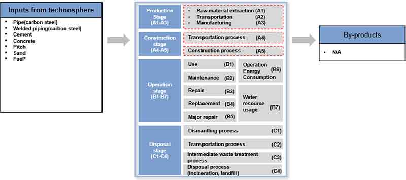
본 연구의 대상은 천연가스 및 수소 파이프라인 1 km 시공 시 발생하는 온실가스 배출량을 평가하는 것으로 시스템의 경계는 Fig. 1에 나타낸 바와 같이 원료 채취, 자재 생산 및 시공까지로 하였다. 현재 수소 파이프라인은 도입 단계로 이에 대한 설계 요구사항을 특정할 수 없으나 미국의 아르곤 국립 연구소(Argonne National Laboratory)에 따르면 천연가스 파이프라인과 유사하므로 천연가스 파이프라인 관련 데이터를 수집하여 전과정평가(life cycle assessment, LCA) 참고 자료로 활용하였다14).
천연가스 및 수소 파이프라인의 시스템 경계 설정은 각각 Table 1과 Table 2에 나타내었다. 수소 파이프라인 시공을 대상으로 하였으므로 수소 생산에 대한 부분은 경계에서 제외하였으며 LCA 수행은 국제 규격인 ISO 14040 및 14044를 따랐다.
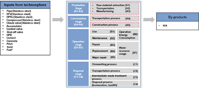
파이프라인 시공 단계는 생산 단계(A1-A3)와 시공 단계(A4-A5)로 구성된다(Figs. 2, 3). 생산 단계는 원재료 채취, 원재료 운송 및 제조 단계로 이루어져 있으며 시공 단계는 운송과 시공 과정으로 구분된다.
투입물은 파이프의 소재 및 부자재에 따라 달라지며 이를 제외한 시멘트, 콘크리트, 모래 및 건설에 사용되는 연료는 각 파이프라인 공정이 유사하므로14) 본 연구에서는 투입물이 동일한 것으로 가정하였다. 천연가스 및 수소 파이프라인 각각에 대해 투입물과 산출물을 Fig. 2와 Fig. 3에 나타내었다. 천연가스 파이프라인의 소재는 탄소강(carbon steel)으로 정하고 수소 파이프라인의 소재는 수소 혼입 시 발생 가능한 수소취성 방지를 위하여 스테인리스강을 사용하는 것으로 가정하였다.
본 연구에서는 파이프라인 시공에 대한 LCA 수행을 위하여 천연가스 파이프라인 설치에 대한 에코 인벤트 unit process raw (UPR) 자료를 참고하여 시공 정보와 재료를 확인하였다. 천연가스 파이프라인 설치 시 용접 배관으로 인해 시공에 투입되는 요소도 증가할 것이나 본 연구에서는 재료에만 차이를 두고 각각의 파이프라인 시공 부분은 계산상의 편의를 위하여 동일하게 설정하였다. 본 연구에서 활용한 데이터베이스의 정보는 Tables 3, 4에 나타내었다.
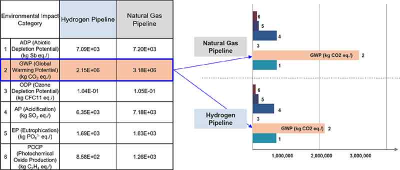
본 연구에서는 환경성적표지(EPD 2013) 영향평가 방법을 기준으로 6개 영향 범주(abiotic depletion potential [ADP], global warming potential [GWP], ozone depletion potential [ODP], acidification potential [AP], eutrophication potential [EP], photochemical oxide creation potential [POCP])에 대해 영향평가를 수행하였다. 환경성적표지에는 물 발자국까지 포함하여 총 7개의 영향 범주가 제시되어 있으나 본 연구의 대상이 되는 원료 취득부터 시공 단계까지는 수질 및 수자원에 미치는 영향이 미미할 것으로 보아 물 발자국을 고려하지 않았다(Fig. 4).
3. 결과 및 고찰
3.1 LCA 수행 결과
LCA 수행 결과 천연가스 파이프라인과 수소 파이프라인을 동일한 길이, 즉 1 km 시공하는 것으로 하였을 때 천연가스 파이프라인의 경우 약 318만 kg CO2eq의 이산화탄소를 배출하며 수소 파이프라인의 경우 약 215만 kg CO2eq의 이산화탄소를 배출한다. 즉 수소 파이프라인 설치 시 천연가스 파이프라인 설치 대비 CO2 저감량, 즉 온실가스 저감 효과는 103만 kg CO2eq이다. 이는 소나무 156,111그루가 연간 흡수하는 이산화탄소 양에 해당하며 이를 Fig. 3에 나타내었다. 산성화(AP)와 광화학 스모그(POCP)에서도 천연가스 파이프라인이 더 높은 영향을 보인다. 오존층 파괴(ODP)의 경우 두 파이프라인 간의 차이는 미미하다. 이를 통해 천연가스 파이프라인이 전반적으로 더 높은 환경 영향을 끼친다는 것을 확인할 수 있다.
Table 5는 천연가스 파이프라인 및 수소 파이프라인 시공 시의 미세먼지 배출량을 나타낸 것이다. 두 파이프라인 모두 입자별(10 µm 이상, 2.5-10 µm, 2.5 µm 미만) 미세먼지 배출량에서는 차이가 없으나 수소 파이프라인 시공 시 천연가스 파이프라인에 비해 94 kg의 먼지 저감 효과가 있는 것으로 나타났다.
4. 결 론
본 연구에서는 탄소중립과 수소 사회 진입에 따라 향후 수소 파이프라인에 대한 수요가 발생 및 증가할 것을 고려하여 기존에 많이 사용되던 천연가스 파이프라인과 새로이 적용될 수소 파이프라인의 환경영향평가를 비교하였다.
파이프라인 1 km 시공 기준 천연가스 파이프라인 대비 수소 파이프라인 설치 시 CO2 저감량은 1.03E+06 kg CO2eq이며 이외에도 94 kg의 먼지 저감 효과가 있는 것으로 나타났다. 천연가스 파이프라인과 비교할 때 수소 파이프라인의 환경적 이점은 온실가스 배출량 감소와 미세먼지 저감 효과 모두 확인되며 이러한 미세먼지 배출량 감소는 대기질 개선에 직접적으로 기여할 뿐만 아니라 미세먼지 저감을 위하여 별도로 동반되는 공정 및 활동에서 추가적으로 온실가스 배출량을 줄이는 간접 효과가 발생한다.
파이프라인 시공에 대한 정확한 LCA 수행을 위해서는 설계 자료 및 시공 정보가 필요하나 본 연구에서는 이를 확보하지 못하여 천연가스 파이프라인 설치에 대한 에코 인벤트 UPR 자료를 참고하여 시공 정보와 재료를 확인하였다. 파이프라인 설치 시 용접 배관으로 인하여 시공에 투입되는 요소도 증가할 것이나 해당 연구에서는 재료에만 차이를 두고 각각의 파이프라인 시공 부분은 계산상의 편의를 위해 동일하게 설정한 한계점이 있다.
그러나 이러한 한계점에도 불구하고 파이프라인 시공 시 파이프라인의 재질에서 비롯되는 온실가스 배출량 차이가 상당하여 이에 대한 환경성 비교 연구는 여전히 의의가 있다. 탄소강은 철광석과 코크스를 사용하여 고로(blast furnace)에서 제련되며 이 과정에서 많은 양의 CO2가 배출되는 탄소 집약적인 공정15)이라는 점에서 주로 재활용된 강철 스크랩과 니켈, 크롬 같은 합금을 사용하는 스테인리스강의 생산 과정의 CO2 배출량이 더 적다. 특히 재활용된 스크랩을 많이 사용할 경우 배출량이 크게 줄어든다. 스테인리스강 생산은 초기 비용이 더 높고 복잡한 합금 처리 과정이 필요하다는 단점이 여전히 존재하나 CO2 배출량 차이로 인하여 탄소중립 목표를 지향하는 산업에서는 스테인리스강과 같은 저탄소 재질의 활용도 재고가 필요한 상황이다16).
향후 후속 연구에서는 설계 데이터 확보 및 심화된 환경적 요인 분석을 통해 연구의 신뢰도를 높여나갈 계획이다. 또한 수소경제 활성화에 따라 수소 운송량이 증가할 경우를 대비하여 수소 운송 방식 간(파이프라인, 튜브 트레일러, 액화 수소 트레일러) LCA 비교 분석 연구가 필요할 것으로 사료된다.
Acknowledgments
본 연구는 국토교통부/국토교통과학기술진흥원의 지원으로 수행되었음(No. RS-2024-00417444).
References
-
Fuel Cells and Hydrogen 2 Joint Undertaking, “Hydrogen roadmap Europe: a sustainable pathway for the European energy transition”, Publications Office of the European Union, Luxembourg, 2016.
[https://doi.org/10.2843/341510]

- United States Department of Energy Office of Fossil Energy, “Hydrogen strategy: enabling a low-carbon economy”, United States Department of Energy Office of Fossil Energy, 2020. Retrieved from https://www.energy.gov/sites/prod/files/2020/07/f76/USDOE_FE_Hydrogen_Strategy_July2020.pdf, .
- Ministry of Trade, Industry and Energy (MOTIE), “Hydrogen economy activation roadmap”, MOTIE, 2019. Retrieved from https://www.korea.kr/briefing/pressReleaseView.do?newsId=156313631&utm_source=chatgpt.com, .
- S.W. Park, “Developing a Life cycle assessment platform to advance hydrogen utilization technonology”, Monthly Hydrogen Economy, 2024. Retrieved from https://www.h2news.kr/news/articleView.html?idxno=13128, .
-
S. J. Jang, D. W. Jung, J. Y. Kim, Y. W. Hwang, and H. K. An, “An evaluation of net-zero contribution by introducing clean hydrogen production using life cycle assessment”, Journal of Hydrogen and New Energy, Vol. 35, No. 2, 2024, pp. 175-184.
[https://doi.org/10.7316/JHNE.2024.35.2.175]

-
H. Kim, Y. Baek, and W. Won, “Techno-economic analysis and life-cycle assessment for the production of hydrogen from biogas”, Journal of Hydrogen and New Energy, Vol. 32, No. 5, 2021, pp. 417-429.
[https://doi.org/10.7316/KHNES.2021.32.5.417]

-
D. W. Yim, “Governance leadership for hydrogen economy revitalization” Journal of Hydrogen and New Energy, Vol. 31, No. 3, 2020, pp. 265-275.
[https://doi.org/10.7316/KHNES.2020.31.3.265]

-
C. Wulf, M. Reuß, T. Grube, P. Zapp, M. Robinius, J. F. Hake, and D. Stolten, “Life cycle assessment of hydrogen transport and distribution options”, Journal of Cleaner Production, Vol. 199, 2018, pp. 431-443.
[https://doi.org/10.1016/j.jclepro.2018.07.180]

-
M. S. Akhtar and J. J. Liu, “Life cycle assessment of green hydrogen transportation and distribution pathways”, Computer Aided Chemical Engineering, Vol. 49, 2022, pp. 1897-1902.
[https://doi.org/10.1016/B978-0-323-85159-6.50316-X]

- Korea Institute of Energy Research, “Research on building a foundation for the realization of the future hydrogen economy: establishment of hydrogen supply infrastructure in the Ministry of Land, Infrastructure and Transport”, Ministry of Land, Infrastructure and Transport, 2019, pp. 50. Retrieved from https://scienceon.kisti.re.kr/srch/selectPORSrchReport.do?cn=TRKO202100022789, .
- H. B. Kwon and S. Y. Jang, “State-of-the-art and prospects on tube transportation technology for development of environment-friendly future transportation system”, Computational Structural Engineering, Vol. 23, No. 3, 2010, pp. 87-96. Retrieved from https://koreascience.kr/article/JAKO201029848350576.pdf, .
- C. G. Lee, “Renewable energy and hydrogen pipeline”, Gas Newspaper, 2023. Retrieved from https://www.gasnews.com/news/articleView.html?idxno=110239, .
- D. G. Kim and B. C. Hwang, “Pipeline steel technology trend for hydrogen energy transportation”, KEIT PD Issue Report, Vol. 21, No. 8, 2021, pp. 66-76. Retrieved from https://images.keit.re.kr/keit_letter/down/20210831_05.pdf, .
-
J. L. Gillette and R. L. Kolpa, “Overview of interstate hydrogen pipeline systems”, Argonne National Laboratory, 2007, pp. 1-40. Retrieved from https://corridoreis.anl.gov/documents/docs/technical/apt_61012_evs_tm_08_2.pdf, .
[https://doi.org/10.55274/R0011902]

-
G. E. Kim, H. S. Oh, J. H. Lee, Y. J. Park, Y. B. Lee, J. H. Kwon, and B. C. Kim, “Development of alternative reductant using biomass for reducing CO2 in ironmaking process”, Korean Journal of Metals and Materials, Vol. 61, No. 3, pp. 218-230.
[https://doi.org/10.3365/KJMM.2023.61.3.218]

- Worldstainless, “Stainless steel CO2 emissions report”, World stainless, 2024. Retrieved from https://www.worldstainless.org/news/stainless-steel-co2-emissions-report-1/, .


