A Numerical Analysis of Pressure Distribution and Pressure Drop in Receptacle for Hydrogen Charging System
2023 The Korean Hydrogen and New Energy Society. All rights reserved.
Abstract
This study analyzes pressure distribution and pressure drop in the receptacle used in charging system of hydrogen fuel cell vehicles. The objective is to minimize receptacle-induced pressure drop by redesigning internal flow channels. Through numerical simulations, three receptacle variants are compared with a baseline case. Results show reduced pressure drop in the filter section. However, the check valve section exhibits higher pressure drop, requiring further improvement. By increasing throat diameter, pressure drop is decreased by 28% between inlet and outlet of the receptacle. This study shows the relationship between dynamic pressure and pressure drop, providing a guideline for receptacle performance optimization. The redesigned receptacle offers potential for enhancing hydrogen charging efficiency.
Keywords:
Receptacle, Pressure distribution, Pressure drop, Filter, Check valve키워드:
리셉터클, 압력 분포, 차압, 필터, 체크밸브1. Introduction
Rising global concerns over the emissions of pollutants from classical internal combustion engines have prompted implementation of stricter exhaust emission regulations1,2). As a result, there has been a growing demand for environment-friendly vehicles to replace conventional internal combustion engine vehicles. Hydrogen fuel cell electric vehicles (FCEVs) have emerged as a promising alternative by utilizing hydrogen as a clean energy source. The purity and cleanliness of the hydrogen fuel are essential to maintain the optimal performance and longevity of fuel cell systems in FCEVs3,4). International standards and regulations have been established to address this issue to govern the quality of hydrogen gas used in refueling systems5). Various purification and filtration technologies, including receptacles equipped with filters, are employed to remove or reduce these impurities and ensure the delivery of high-quality hydrogen fuel to FCEVs. Consequently, extensive study has focused on improving receptacle performance by optimizing refueling efficiency.
The receptacle plays a crucial role as a critical component in hydrogen refueling systems. Its internal configuration significantly influences fluid behavior during refueling. Ye et al6,7). investigated the effect of the spool-head angle and shape of receptacles on the movement performance of the valve spool and flow field characteristics. The structural optimization of the check valve was conducted by them. To minimize the vibration and noise induced by the receptacle, Lee et al8). employed two different valve models and conducted numerical analyses under varying flow conditions. They successfully demonstrated that alterations in the channel shape led to reduced vibration and noise levels. Choi et al9). studied the internal flow of the receptacle and found that reducing the diameter of the poppet is advantageous for improving performance. These studies collectively establish significant influence of internal variations on the performance of the receptacle.
In this study, the objective is to investigate the pressure drop caused by the receptacle. The research aimed to reduce the pressure drop by analyzing the pressure distribution within the internal flow channel. A comparison is made between the re-designed variants and the baseline receptacle to assess the differences in pressure drop. Additionally, the relationship between the cross-sectional area of the flow channel, dynamic pressure, and pressure drop is examined and discussed. The outcomes of this study offer valuable insights and serve as essential reference criteria for optimizing the performance of the receptacle, thereby contributing to advancements in hydrogen refueling technology.
2. Numerical methodology
2.1 Geometry and mesh grids
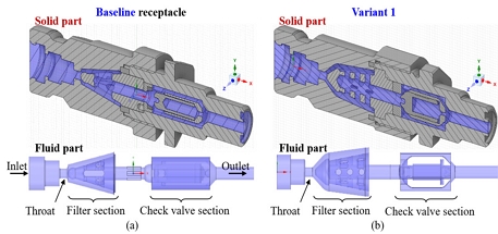
Fig. 1 illustrates the geometric models of the existing baseline receptacle, its variant, and their internal flow channels. High-pressure hydrogen gas is supplied through the inlet, passes through the receptacle, and enters the vehicle's hydrogen storage tank10). The filter section accommodates a filtration mesh to remove contaminants from the supplied hydrogen gas. After filtering, the gas flows through the check valve and is injected into the storage tank. As the flow passes through the filter and check valve section, the significant pressure drop occurs due to the variations of cross-section area and flow direction. Consequently, these two components require particular attention and consideration when redesigning the receptacle.
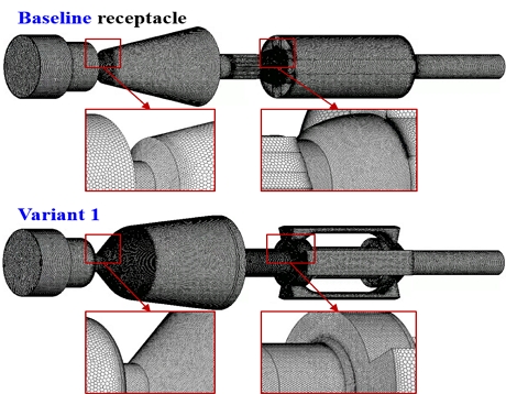
Fig. 2 shows the mesh grids of the baseline receptacle and receptacle variants generated for numerical simulations. Polyhedral-type meshes are utilized for all grids. Mesh refinement was employed in regions of significant flow variations, such as the throat preceding the filter and the head of the check valve. The total number of cell grids is approximately 2.46 million. Before conducting numerical simulations, a grid dependency analysis was performed, revealing that the pressure variation at the receptacle outlet caused by differences in the mesh was within 0.5%. It shows that the mesh grids used in this study can provide reasonably accurate results.
2.2 Boundary condition
The design condition for the receptacle is set at 70 MPa and -40℃. Therefore, the inlet condition of the receptacle is specified as a pressure inlet at 70 MPa, while the outlet condition is set as a mass flow outlet to calculate the pressure variation. All the information is listed in Table 1.
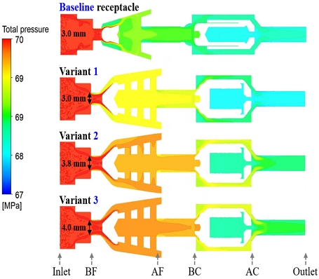
The throat, located between the inlet and filter section, is where the gas experiences the first flow variation due to a reduction in the path diameter. Therefore, the impact of throat diameter on pressure drop is studied. The baseline receptacle has a throat diameter of 3 mm, while the three variants have throat diameters of 3, 3.8, and 4 mm, respectively.
As shown in Table 2, the density of hydrogen is calculated using the real-gas law. Other properties, such as specific heat capacity, thermal conductivity, and viscosity, are determined using known polynomial models11).
2.3 Numerical model
The continuity, momentum, and energy equations are summarized in generalized vector forms as follows:
| (1) |
| (2) |
| (3) |
where ρ is density, t is time, v is velocity, p is the static pressure, is the stress tensor, is the gravitational body force, is external body force, E is the total energy, hi and Jj are the enthalpy and mass flux of species j, and Sh is the source term.
To simulate turbulent flow, the above equations (1)-(3) are transformed to Reynolds-averaged Navier-Stokes equations, which form is well known on the basis of k-ω turbulent models. All simulations in this study are conducted using the general-purpose computational fluid dynamics code12). The shear stress transport k-ω turbulent model is adopted. For spatial discretization of the partial differential equations, the second order upwind scheme is employed.
3. Results and discussion
3.1 Total pressure distribution
Fig. 3 shows the total pressure distribution from the receptacle inlet to the outlet. Both the baseline receptacle and the three variants exhibit the same pressure variation process. The color representing pressure magnitude reveals that pressure drops occur at the throat firstly, where the flow passage diameter abruptly decreases. Furthermore, after passing through the filter section, a pressure reduction is observed. And the pressure further decreases as the fluid continues through the check valve section. After the check valve, there is a final pressure drop before reaching the receptacle outlet.
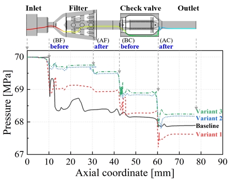
Fig. 4 provides a detailed depiction of the pressure drop process along a streamline from the receptacle inlet to the outlet. To describe the pressure changes, several specific positions are defined: the inlet, before the filter (BF), after the filter (AF), before the check valve (BC), after the check valve (AC), and the outlet. From Fig. 4, it is seen that the pressure changes from the inlet to BF are relatively minor. However, a sharp pressure drop occurs after BF. Subsequent pressure reductions are observed at AF, BC, and AC. Significant pressure drops are observed between BF and AF, as well as between BC and AC. Therefore, detailed observations and analysis of the filter and the check valve section are necessary.
3.2 Flow inside the filter and check valve sections
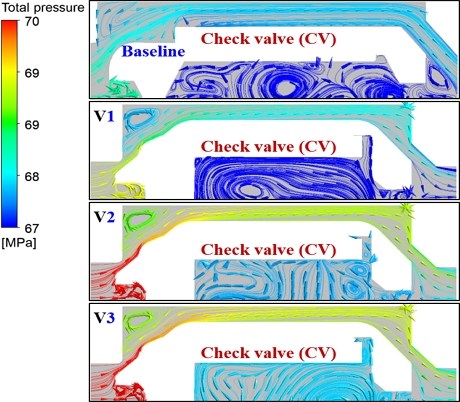
Fig. 5 illustrates the streamline and pressure variations in the filter section. It can be observed that there is a pressure gradient starts from the throat. After entering the filter, two recirculation zones, RZ1 and RZ2 are formed. RZ1 exhibits a more pronounced pressure gradient distribution. RZ2 is formed as the fluid passes through the filter, but the pressure change in this region is minimal.
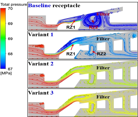
Streamlines and pressure distribution in the filter section of the baseline receptacle and three receptacles
Similarly, the streamline and pressure variations in the check valve section can be seen in Fig. 6. The upstream fluid pushes the valve, causing it to open and form a flow passage. Velocity changes occur when the check valve head is impacted, resulting in corresponding pressure gradient distributions. Three variants exhibit more pronounced pressure gradient distributions, as their cross-sectional areas of the check valve section are smaller than the baseline receptacle.
3.3 Analysis of pressure drop
For a horizontal pipe, the Darcy-Weisbach equation can be used to calculate the main pressure drop as follows13):
| (4) |
| (5) |
where f is the friction factor, l is the pipe length, d is the diameter, ρ is the fluid density, v represents fluid velocity, Re, the Reynolds number, and ϵ/D is the relative roughness.
For a valve, the additional pressure drop associated with flow is a common minor loss, can be calculated with the following equation13):
| (6) |
where KL is the loss coefficient.
From equations (4) and (6), it can be seen that if the f and KL are constant values, the pressure drop will exhibit a direct proportionality to 1/2ρv2, which is the dynamic pressure term of Bernoulli’s equation13). In this study, the pressure and temperature are the same for all cases, and the geometries of the baseline receptacle and variants are also similar. Therefore, it can be assumed that there is not much difference in f and KL. Thus, the pressure drop mainly comes from the variation in dynamic pressure.
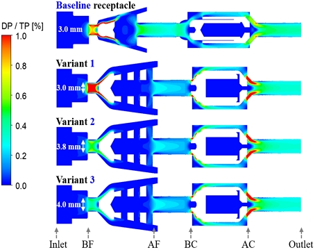
Fig. 7 illustrates the percentage of dynamic pressure contribution to the total pressure in each receptacle. It can be observed that the percentage of dynamic pressure at BF is relatively high, corresponding to the significant variations in pressure shown in Fig. 5. Among the three variants, when the throat diameter increases, the decrease in velocity change and the reduction in dynamic pressure result in a lowered pressure drop near the throat. Moreover, it's evident that in the AF position of the receptacle, the dynamic pressure in all three variants is lower compared to the baseline. However, at the check valve, the cross-sectional areas of the variants’ BC and AC are smaller than that of the baseline receptacle, resulting in higher pressure drops.
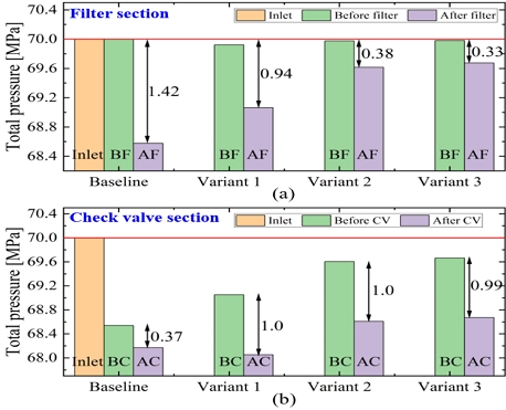
Fig. 8 presents the magnitude of pressure drop through the filter and check valve sections. From Fig. 8(a), it can be observed that the pressure drop generated by the variant’s filter section is lower than that of the baseline. The filter section of variant 1, which has the same diameter as the baseline, results in a 33.8% lower pressure drop than baseline. Furthermore, as the throat diameter of variants increases, the pressure drop decreases. Modifying the filter section's internal flow channels and increasing the throat diameter can reduce the pressure drop from the initial 1.42 to 0.33 MPa.
In Fig. 8(b), it can be seen that the pressure drop caused by the check valve in the baseline configuration is 0.37 MPa, whereas the pressure drop across the check valves of three variants is approximately 1 MPa. It can be concluded that the baseline check valve performs better. This implies that when improving the variants in the future, special attention should be given to the flow passage at the check valve section.
The variation of the area-averaged total pressure at six positions (inlet, BF, AF, BC, AC, and outlet) in the receptacle is shown in Fig. 9. The baseline receptacle exhibits a significant pressure drop in the filter region and a smaller pressure drop at the check valve region, resulting in a total pressure drop of 1.91 MPa from inlet to outlet. In variant 1, the pressure drop in the filter region is slightly smaller than that of the baseline receptacle, but the pressure drop at the check valve region is higher, resulting in a total pressure drop of 2.18 MPa, which is higher than the baseline. In variant 2 and variant 3, the pressure drop in the filter section is further reduced with an increase in throat diameter. As a result, even though the pressure drop in the check valve region remains the same as in variant 1, the total pressure drops in variant 2 and variant 3 are lower than the baseline, which are 1.63 and 1.56 MPa, respectively. Comparing variant 3 with variant 1, by increasing the throat diameter by 1 mm, the total pressure drop is reduced by 0.62 MPa, representing a 28% reduction.
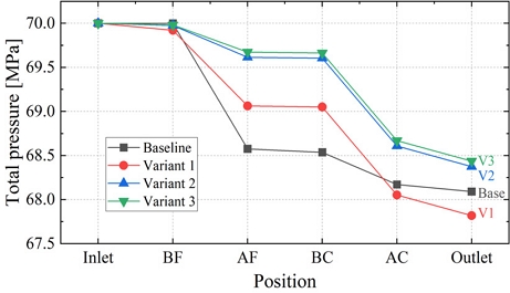
Area-averaged total pressure at six positions in four receptacles: inlet, before filter (BF), after filter (AF), before check valve (BC), after check valve (AC), and outlet
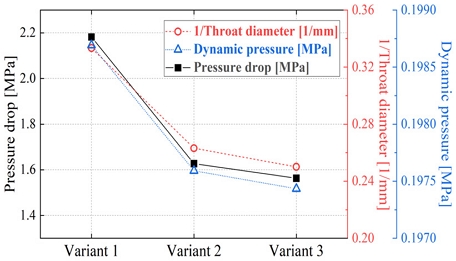
Fig. 10 illustrates the inverse relationship between dynamic pressure and pressure drop with throat diameter. This observation provides validation for the earlier notion that the pressure drop mainly comes from the variation in dynamic pressure. As the throat diameter increases, the cross-sectional area of the flow passage expands, leading to a reduction in fluid velocity.
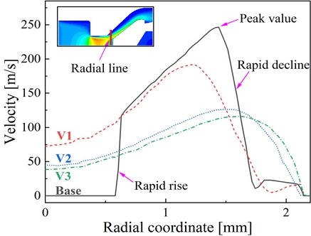
Additionally, the reduced angle of the flow passage at the filter head results in a gentler change in fluid direction, contributing to the velocity reduction. This can be observed from Fig. 11. In the baseline case, there is a noticeable rapid rise and decline in velocity changes in the radial direction, and a largest peak value. However, in the variants, by adjusting the angle of the flow path at the rear of the throat, the velocity changes become smoother, and with larger throat diameters, the velocity changes become even gentler. These alterations in velocity magnitudes and distributions contribute to reducing pressure losses.
The decrease in flow velocity indicates a gradual diminution of dynamic pressure. As per Equation 6, it can be deduced that pressure drop decreases in line with the reduction in dynamic pressure, consistent with the trend shown in Fig. 10. Based on this trend, further research can focus on optimizing the check valve's flow passage to enhance the receptacle's performance. By carefully designing and adjusting these parameters, it is possible to achieve reduced pressure drop and improved overall efficiency.
4. Conclusion
In this study, the internal flow passage of the receptacle was redesigned based on the baseline receptacle as a reference. The pressure drop between the baseline receptacle and the variants was compared. The findings are as follows:
1) The results demonstrate that the performance of the variant's filter outperforms the baseline receptacle. However, there is still room for improvement in the check valve compared to the baseline. Under the same throat diameter, the pressure drop in the variant's filter region is 33.8% lower than that of the baseline receptacle.
2) After adjusting the throat diameter, the total pressure drop at the inlet and outlet of the variant is reduced by 28% compared to the baseline receptacle.
3) It was also observed that the pressure drop is directly proportional to the dynamic pressure. When the flow passage area increases, the velocity variation of the fluid becomes uniform, leading to a decrease in both the dynamic pressure and friction generated by the flow, resulting in a reduced pressure drop.
Although this study focused solely on adjusting the throat diameter, the obtained results and the observed trend in pressure drop variations provide valuable insights for future optimization of the internal flow passage in the receptacle.
Acknowledgments
This study was supported by research funding from the Ministry of Trade, Industry, and Energy (MOTIE) and the Korea Evaluation Institute of Industrial Technology (KEIT) in 2023 (Project No. 20015788).
References
-
A. Albatayneh, A. Juaidi, M. Jaradat, and F. Manzano-Agugliaro, “Future of electric and hydrogen cars and trucks: an overview”, Energies, Vol. 16, No. 7, 2023, pp. 3230.
[https://doi.org/10.3390/en16073230]

-
A. Joshi, “Review of vehicle engine efficiency and emissions”, SAE International journal of advances and current practices in mobility, Vol. 4, No. 5, 2022, pp. 1704-1733.
[https://doi.org/10.4271/2022-01-0540]

-
L. Fan, Z. Tu, and S. H. Chan, “Recent development of hydrogen and fuel cell technologies: a review”, Energy Reports, Vol. 7, 2021, pp. 8421-8446.
[https://doi.org/10.1016/j.egyr.2021.08.003]

-
D. Guilbert and G. Vitale, “Hydrogen as a clean and sustainable energy vector for global transition from fossil-based to zero-carbon”, Clean Technologies, Vol. 3, No. 4, 2021, pp. 881-909.
[https://doi.org/10.3390/cleantechnol3040051]

-
D. Kim, J. S. Lim, and J. Lee, “Current status of standardization for quality control of hydrogen fuel in hydrogen refueling stations for fuel cell electric vehicles”, Journal of Hydrogen and New Energy, Vol. 33, No. 4, 2022, pp. 284-292.
[https://doi.org/10.7316/KHNES.2022.33.4.284]

-
J. Ye, Z. Zhao, J. Cui, Z. Hua, W. Peng, and P. Jiang, “Transient flow behaviors of the check valve with different spool-head angle in high-pressure hydrogen storage systems”, Journal of Energy Storage, Vol. 46. 2022, pp. 103761.
[https://doi.org/10.1016/j.est.2021.103761]

-
J. Ye, J. Cui, Z. Hua, J. Xie, W. Peng, and W. Wang, “Study on the high-pressure hydrogen gas flow characteristics of the needle valve with different spool shapes”, International Journal of Hydrogen Energy, Vol. 48, No. 30, 2023, pp. 11370-11381.
[https://doi.org/10.1016/j.ijhydene.2022.04.073]

- J. Lee, S. Han, H. Kim, G. Kim, and J. Kim, “Numerical study for flow noise reduction of receptacle for hydrogen charging in FCEV”, 2018 KSAE Annual Conference, Vol. 2018, 2018, pp. 186. Retrieved from https://www.dbpia.co.kr/journal/articleDetail?nodeId=NODE07593039&nodeId=NODE07593039&medaTypeCode=185005&language=ko_KR&hasTopBanner=true, .
-
J. H. Choi, G. H. Kim, J. K. Kim, Y. K. Kim, and H. K. Suh, “Analysis of flow performance according to actuator geometry of receptacle for hydrogen charging system with filter applied”, Journal of Hydrogen and New Energy, Vol. 34, No. 1, 2023, pp. 17-25.
[https://doi.org/10.7316/KHNES.2023.34.1.17]

-
J. Q. Li, H. Xu, J. C. Li, and J. T. Kwon, “A theoretical study on the compressibility factor of hydrogen gas in the high pressure tank”, Journal of Hydrogen and New Energy, Vol. 34, No. 2, 2023, pp. 162-168.
[https://doi.org/10.7316/JHNE.2023.34.2.162]

- ANSYS, “ANSYS Fluent theory guide: release 2021 R2”, ANSYS, 2021. Retrieved from https://dl.cfdexperts.net/cfd_resources/Ansys_Documentation/Fluent/Ansys_Fluent_Theory_Guide.pdf, .
- ANSYS, " ANSYS Fluent user guide : realese 13.0", ANSYS, 2010. Retrived from https://www.fluid.tuwien.ac.at/322057?action=AttachFile&do=get&target=flu_ug.pdf, .
- B. R. Munson, T. H. Okiishi, W. W. Huebsch, and A. P. Rothmayer, “Fundamentals of fluid mechanics”, 7th ed., John Wiley & Sons, USA, 2013.
