고온 고분자 막 전해질 연료전지 캐소드의 가스 확산층 및 바인더 함량에 따른 완화 시간 분포(DRT) 저항 분석
2023 The Korean Hydrogen and New Energy Society. All rights reserved.
Abstract
The physical properties were analyzed for four gas diffusion layers, and gas diffusion electrodes (GDEs) for the cathode of high-temperature polymer electrolyte membrane fuel cell were fabricated through bar coating with three binder to carbon (B/C) ratios. Among them, The GDE from JNT30-A6P showed a significant change in secondary pore volume at a B/C ratio of 0.31, which had the largest pore volume among all GDEs. In the polarization curve, JNT30-A6P GDE showed the best membrane electrode assembly (MEA) performance with a peak power density of 384 mW/cm2 at a a B/C ratio of 0.31. From the distribution of relaxation time analysis, the peak 1 corresponding to mass transfer resistance of oxygen reduction reaction (ORR) was significantly reduced in the JNT30-A6P GDE. This is the result that when the binder content decreased, the volume of the secondary pore increased, and the mass transfer resistance of ORR decreased, which played an essential role in the MEA performance.
Keywords:
High-temperature polymer electrolyte membrane fuel cell, Gas diffusion layer, Distribution of relaxation time, Mass transfer resistance, Gas diffusion electrode키워드:
고온 고분자 막 전해질 연료전지, 가스 확산층, 완화 시간 분포, 물질 전달 저항, 가스 확산 전극1. 서 론
2015년 제정된 파리 협정 이후 선진국을 중심으로 각 나라들은 에너지의 탈탄소화를 이루기 위해 부단한 노력을 기울이고 있다. 이러한 경향은 운송, 발전, 난방 등 다양한 영역에서 나타나지고 있다1).
고온(high temperature, HT) 고분자 막 전해질 연료전지(polymer electrolyte membrane fuel cell, PEMFC)는 150℃ 이상의 온도에서 인산 기반 전해질을 사용하는 연료전지이다2). 저온(low temperature) PEMFC와의 가장 큰 차이는 작동 온도의 증가로 인한 막과 전해질이다. 저온 연료전지에서 주로 사용되는 Nafion® 계열의 막은 100℃ 이상의 고온에서 성능이 급격히 저하되고, 이 온도에서 물은 액체 상태로 존재할 수 없어서 무가습 조건에서 수소 이온을 전달할 수 있는 인산 전해질과 폴리벤조이미다졸(polybenzoimidazole, PBI) 계열의 막이 사용된다3,4). 막 전극 접합체(membrane electrode assembly, MEA) 내부 전극에서는 반응물인 산소 및 수소와 생성물인 물의 이동 및 전기화학 반응이 일어난다. 따라서 전극 소재는 연료전지의 성능 및 내구성에 있어서 큰 영향을 미친다5). 전극은 크게 가스 확산층(gas diffusion layer, GDL)과 촉매층(catalyst layer, CL)으로 구별된다. 치은 촉매와 함께 촉매를 층 형태로 고정시킬 수 있는 바인더 물질로 이루어져 있다. GDL은 분리판에서 촉매층으로 반응물 가스를 균일한 농도로 전달하는 통로이며 carbon paper 혹은 carbon cloth로 이루어진 가스 확산층 기재(gas diffusion back layer, GDBL)와 탄소 소재로 이루어진 미세 기공층(microporous carbon layer, MPL)으로 구성된다. GDBL 위에 탄소 입자로 이루어진 MPL은 소수성을 확보하고 기공 구조를 제어하여 기체를 고르게 확산시키면서 CL의 코팅을 쉽게 해주는 역할을 한다6,7).
PEMFC에서 작동 중 발생하는 저항 성분을 분리 분석하기 위해서 전기화학 임피던스 분광법(electrochemical impedance spectroscopy, EIS)이 널리 이용되고 있다. EIS는 주파수에 따라서 연료전지 작동 중 발생하는 저항을 옴(Ohm) 저항(Rohm), 애노드(anode) 저항(Ranode), 캐소드(cathode) 저항(Rcathode)으로 나누어 Nyquist plot 혹은 Bode plot으로 나타낸다8). 이 과정에서 연료전지 시스템을 저항(resistance, R)과 캐퍼시터(capacitor) 성분들로 이루어진 등가 회로로 모사하여 나타낸다. 2010년대에 들어 EIS보다 더 세분화되고 신뢰도 높은 분석법인 완화 시간 분포(distribution of relaxation time, DRT) 기법이 연료전지 및 배터리 등의 전기화학 시스템에 적용되고 있다9-14). DRT는 EIS의 데이터(data)인 임피던스 Z(ω) 값을 retention time (τ)에 대하여 무한한 등가 회로로 모사하여 나타내는 방법이다. 이때 임피던스와 τ의 관계식은 식 (1), (2)과 같다.10-14)
| (1) |
| (2) |
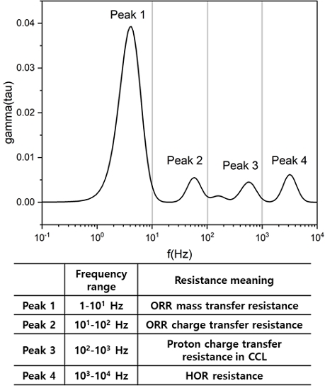
선행 연구들에서 DRT를 통한 HT-PEMFC의 저항 성분의 분포는 제시되어 있으며 이는 Fig. 1과 같다. 1부터 10 Hz 영역에서 나타나는 peak 1은 oxygen reduction reaction (ORR) mass transfer, 10부터 100 Hz 영역에서 나타나는 peak 2는 ORR charge transfer, 100부터 1,000 Hz 영역에서 나타나는 peak 3은 CL에서의 수소 이온 전도에 의한 저항, 1,000 Hz보다 더 고주파 영역에서 나타나는 peak 4는 애노드 및 막에서 일어나는 수소 이온 전도에 의한 저항에 해당한다. 이 때 각 peak의 면적을 peak의 중앙 x값으로 나눈 값이 해당 저항 성분의 저항값(Ω)을 나타낸다15).
본 연구에서는 JNTG 사의 MPL 및 GDBL의 종류가 다른 4종류의 국산 GDL (JNT20-A3, JNT20-A6L, JNT30-A3, JNT30-A6P; JNTG, Hwaseong, Korea)을 선정하였다. JNT20과 30은 GDBL의 차이를 의미하며 A3와 A6L, A6P는 MPL의 세대 차이를 의미하고 후자가 차세대 MPL층을 의미한다. 먼저 GDL의 물리적 특성 및 기공 분포에 대해 분석하였다. 또한, 이에 대해 3가지 바인더/카본(binder/carbon, B/C) 질량 비율(B/C ratio)에 따라서 bar coating하여 캐소드를 제조한 후에 성능을 비교하고, DRT 분석을 통해서 GDL에 따라 B/C ratio가 성능에 어떤 영향을 미치는지 분석하였다.
2. 실험 방법
2.1 캐소드 가스 확산 전극 제조
서로 다른 네 종류의 GDL에 대해 바인더로서 polyvinylidene fluoride (Sigma-Aldrich, St. Lousis, MO, USA)와 이를 분산시키는 용매로서 N-methyl-2-pyrrolidone (Daejong, Siheung, Korea)이 사용되었다. 캐소드 촉매로는 50 wt.% PtCo/C (TEC36F52; Tanaka Kikinzoku Kogyo K.K., Tokyo, Japan)를 사용하여 바인더 및 용매와 ball-mill (PM100; Retsch, Haan, Germany)을 이용해 250 rpm에서 1시간 동안 균일하게 혼합하였고, bar coater (KP-3000VH; KIPAE E&T, Hwaseong, Korea)를 이용하여 10 mm/s의 속도로 GDL에 1 mg/cm2 로딩량으로 코팅하였다. 이때 각각의 GDL에 대해서 0.53 (high), 0.43 (mid), 0.32 (low)의 B/C ratio로 캐소드 가스 확산 전극(gas diffusion electrode, GDE)을 제작하였다.
2.2 전극의 물리적 특성 분석
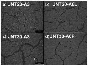
GDL 표면 사진은 광학 현미경(Camscope; Sometech, Seoul, Korea)을 사용하여 300배율로 촬영되었다(Fig. 2). GDL 접촉각은 contact angle analyzer (UNI-CAM.M; GIT software, Amsterdam, Netherlands)를 사용하여 측정되었다. GDL 및 GDE 기공 분석은 수은 압입 기공 측정법(mercury intrusion porosimetry)을 이용하여 측정되었다.
2.3 MEA 제작 및 전기화학적 특성 분석
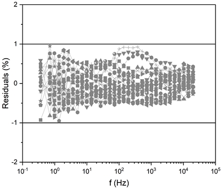
제작된 GDE가 캐소드로 사용되었으며, 전해질 막으로는 PBI-based membrane (Dongjin Semichem, Seoul, Korea)을 60℃ 조건에서 6시간 85 wt.% 인산(Daejong, Siheung, Korea)에 함침시켜 사용하였다. 애노드로는 상용 GDE (Pt loading 1 mg/cm2; Dongjin Semichem, Seoul, Korea)를 사용하였다. 활성 면적은 7.84 cm2이 되도록 MEA를 체결하였고, 단위 전지 평가 장치(Scitech Korea, Seoul, Korea)를 이용하여 H2/air 100/300 sccm, 150℃ 조건에서 성능을 I-V curve로 측정하였다. EIS는 모든 샘플에서 동일하게 0.6 V potentiostatic 모드에서 100 mHz에서 10 kHz까지 측정하였다. Supplementary Fig. 1은 측정된 Nyquist plot에 대하여 Kramers-Kronig 유효성 검사를 통해 모든 임피던스 데이터들의 유효성 평가이다. 또한 Matlab 프로그램을 이용하여 Gaussian method를 통해 EIS 그래프를 DRT로 변환하여 분석하였다.
3. 결과 및 고찰
3.1 전극의 물리적 특성 분석
Fig. 2는 4종의 GDL에 대하여 표면을 300배 확대하여 촬영한 사진이며 Table 1은 접촉각, 두께, 공극률을 각각 나타낸 값이다. GDBL에 따라 JNT20 계열은 약 250 μm, JNT30 계열은 이보다 두꺼운 310-330 μm의 두께를 가진다. 또한 JNT20 계열에 비해 JNT30 계열의 GDL이 더 소수성을 가지는 것으로 측정되었다.
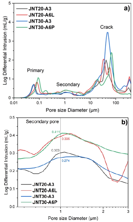
Fig. 3은 GDL의 기공 크기 분포(pore size distribution)를 나타내었다. MPL의 종류에 따라서 약 1 μm pore이면서 산소가 이동하는 주요 통로로 알려진 secondary pore의 부피가 달라진 것을 확인할 수 있다16,17). A3 계열의 MPL을 사용한 GDL은 약 0.3 mL/g의 secondary pore가 측정되었고 A6L, A6P GDL은 약 0.4 mL/g을 가진 것으로 측정되었다. 또한 Table 1에서 공극률이 A3 계열에 비해 A6L, A6P 계열이 82%에서 84%로 약 2% 증가한 것을 확인할 수 있다. 이는 차세대 MPL 층을 적용한 GDL들이 secondary pore가 더 발달하여 이로 인해 더 큰 공극률을 가지는 것으로 판단된다. GDBL 내부의 섬유 및 크랙 간격에 따라 달라지는 10 μm 이상 pore의 경우 JNT30-A3가 가장 크게 측정되었다. 이는 Fig. 2의 GDL을 300배 확대한 사진에서 JNT30-A3의 크랙이 크게 촬영된 것과 일치한다.
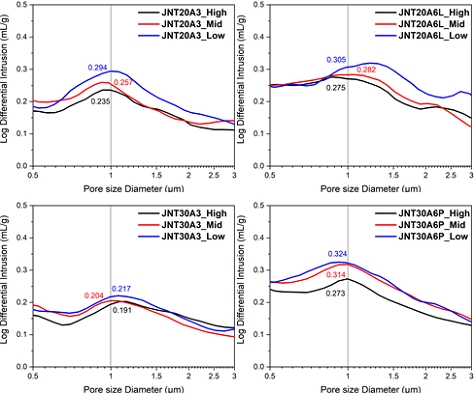
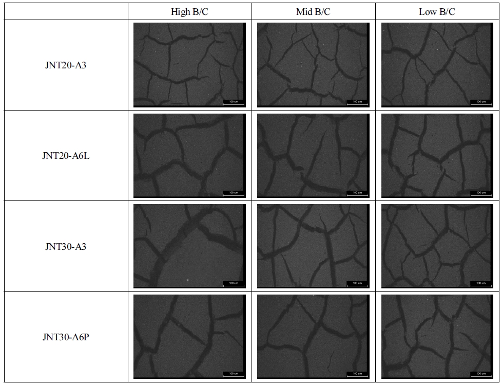
Supplementary Fig. 2는 본 논문에서 캐소드로 사용된 GDE들을 300배 확대하여 촬영한 사진이다. B/C에 상관없이 모든 전극에서 크랙 구조가 형성되며 특히 JNT30 기반의 GDE의 경우 낮은 B/C ratio에서 큰 크랙이 관찰된다. Fig. 4의 수은 기공 분석으로 측정한 GDE의 기공 크기 분포에서 약 1 μm의 secondary pore 영역에서 차세대 MPL을 사용한 GDE의 경우 GDL에 비해서 전체적으로 약 0.1 mL/g의 pore volume이 감소한 것을 확인할 수 있다. 반면, A3 MPL을 사용한 GDE는 그보다 작은 0.06 mL/g 이하로 pore volume이 감소하였다. 모든 GDE에서 공통적으로 B/C ratio가 증가함에 따라 secondary pore가 감소하는 것을 볼 수 있으며, 감소한 정도는 JNT30-A6P를 사용한 GDE에서 약 0.5 mL/g으로 가장 큰 차이를 보였다. 이는 기공이 큰 GDL에서 바인더가 증가함에 따라 기공을 더 많이 막아 secondary pore의 부피를 감소시키는 것으로 분석된다. 또한 전체 GDE 중에서 JNT30-A6P를 사용한 GDE가 가장 큰 secondary pore가 발달한 것을 확인할 수 있다. 해당 GDE의 B/C ratio는 0.321이다. 이는 GDL의 secondary pore volume의 경향성이 GDE에서도 유지되는 것으로 볼 수 있다.
3.2 전기화학적 특성 분석
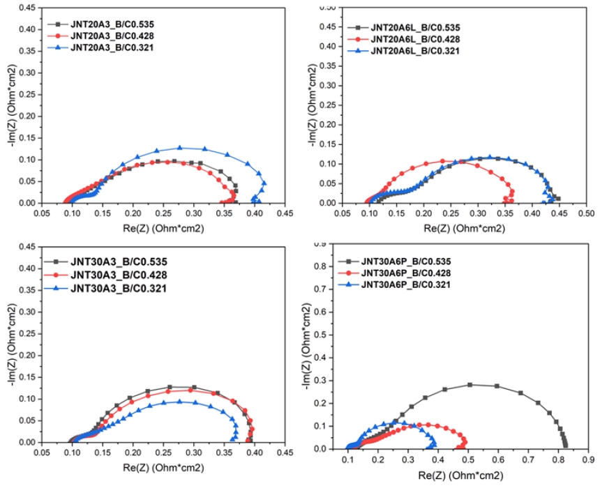
Fig. 5는 GDL별로 세 종류의 서로 다른 B/C ratio를 가진 GDE를 캐소드에 적용한 성능 평가 결과를 I-V curve로 나타내었다. 또한, Table 2에는 I-V curve에서 0.2 A/cm2에서의 전압과 peak power density, Supplementary Fig. 3의 EIS Nyquist plot으로부터 얻은 Rcathode 값, Fig. 6의 DRT 그래프에서 peak 1로부터 구한 저항값을 나타내었다. JNT30-A6P를 사용한 GDE를 제외한 다른 모든 GDL에 대해서 0.43의 B/C ratio로 제작한 GDE가 0.2 A/cm2에서 약 0.65 V, peak power density는 약 370 mW/cm2로 가장 좋은 성능을 보였다. 전체적인 성능의 수준은 이전 연구에서 다른 종류의 GDL을 사용하였을 때와 비슷한 수준을 보인다18). JNT30-A6P를 사용한 GDE의 경우 0.32의 낮은 B/C ratio에서 0.2 A/cm2에서 약 0.649 V, peak power density는 약 384 mW/cm2로 측정되었다. 그리고 JNT20-A6L을 사용한 GDE를 제외한 다른 시료들에서 공통적으로 낮은 B/C ratio에서 높은 peak power density를 보인다. 이는 바인더 함량이 줄어들수록 secondary pore가 잘 발달하여 산소가 전극 내에서 원활히 전달되어 mass transfer에 의한 전압 강하가 작아지기 때문이다19-22). 또한 JNT30-A6P를 사용한 GDE에서 B/C ratio가 커질수록 가장 크게 성능이 감소하는 것을 볼 수 있다. 이때 저전류 밀도 구간에 비해 고전류 밀도 구간으로 갈수록 성능 차이가 커지는 것으로 보아, mass transfer에 의한 전압 강하가 다른 GDL을 사용한 GDE에 비해서 크게 일어나는 것으로 볼 수 있다23,24). Fig. 4에서 B/C ratio가 증가할수록 secondary pore가 크게 감소한 것으로 보아, 앞서 언급한 mass transfer 저항 증가에 의한 성능 감소가 JNT30-A6P GDE에서 더 크다고 할 수 있다. 이러한 결과는 Table 2에서 JNT30-A6P를 사용한 GDE의 경우 B/C ratio가 증가할수록 캐소드 저항이 크게 증가하여 같은 B/C ratio로 제작한 다른 GDL 기반의 GDE들에 비해 높은 캐소드 저항을 보이는 것으로 뒷받침된다. 반면, 다른 세 종류의 GDL을 사용한 GDE는 B/C ratio 변화에 따른 캐소드 저항 차이가 0.01 Ω 이내로 매우 작은 것을 확인하였다. 또한 모든 샘플들은 동일한 막과 애노드를 이용하였기 때문에 비슷한 수준의 옴 저항(약 0.012 Ω) 및 애노드 저항(약 0.006 Ω)을 보였다25).
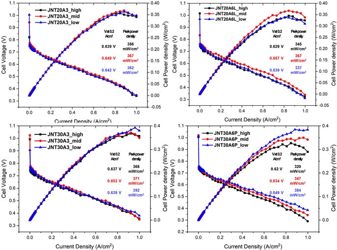
I-V curve and EIS nyquist plot of GDE with three ratios of 0.53 (high), 0.43 (mid), and 0.32 (low) in four types of GDL used as HT-PEMFC cathode
Fig. 6은 Supplementary Fig. 3의 EIS 그래프를 기반으로 계산된 DRT 그래프이다. JNT20-A6L GDL을 사용한 GDE를 제외한 다른 샘플에서는 공통적으로 B/C ratio가 낮아질수록 peak 1의 크기가 감소하는 것을 볼 수 있다. 또한 낮은 B/C ratio의 샘플이 고전류 밀도 구간에서 더 높은 성능을 보인 것으로 보아 바인더 함량이 줄어 ORR mass transfer가 원활해진 것이 peak 1의 크기가 감소한 원인으로 파악될 수 있다26). JNT20-A3 및 JNT30-A3를 이용한 GDE에서 B/C ratio가 감소함에 따라 peak 2의 크기가 증가함을 볼 수 있다. 이는 바인더가 줄어듦에 따라서 촉매가 인산에 피독되는 영향이 커지거나 촉매의 한정적인 active site에 비해 많은 반응물이 공급되어 ORR charge 저항이 증가했기 때문인 것으로 추정된다. 이들은 peak 1과 peak 2의 효과가 양방향으로 작용하여 0.43의 B/C ratio에서 가장 좋은 성능을 보였다. Fig. 6에서 JNT30-A6P를 사용한 GDE에서는 B/C ratio에 의한 peak 1의 증감이 크게 나타나며, Table 2에서 peak 1 R 값이 0.53의 B/C ratio에서 두 배가량 증가했다. 이는 다른 GDE에 비해 JNT30-A6P GDE가 바인더 함량이 증가함에 따라서 산소의 mass tranfer 저항이 급격하게 증가했고, 이로 인해 캐소드 저항이 증가하면서 고전류 밀도 영역에서의 성능이 감소하였음을 의미한다. JNT30-A6P GDE에서 peak 1의 차이가 큰 것은 Fig. 2에서 B/C ratio에 따른 secondary pore의 부피 차이가 컸던 것과 일치하는 경향을 보인다. 이를 통해 이 GDL을 이용한 샘플에서 B/C ratio가 증가함에 따라서 산소의 주요 이동 통로인 secondary pore의 부피가 줄고 이로 인해 ORR mass transfer resistance가 커진 것으로 판단된다. 전체 샘플에서 peak 3 이상의 고주파에서 나타나는 peak는 최적 성능의 B/C ratio에서 가장 작게 나타났으나 그 차이는 peak 1에 비해 미미했으며 성능에 유의미한 차이를 나타내지는 않았다. 따라서 DRT상에서 peak 1의 차이가 본 실험에서 유의미한 성능 차이를 만들었다고 할 수 있으며, 이는 GDL 기공율이 큰 JNT30-A6P에서 가장 두드러진다.
4. 결 론
본 연구에서 네 종류의 GDL (JNT20-A3, JNT-20A6L, JNT-30A3, JNT-30A6P)에 대해서 표면 상태, 접촉각, 두께, 공극률, 기공 분포의 물리적 특성을 파악하였다. 차세대 MPL 층을 사용한 A6L, A6P GDL이 약 2% 높은 공극률을 가지며, secondary pore가 약 0.1 mL/g 높게 측정되었다. GDL들은 bar coating 방식을 통해 0.53, 0.43, 0.31의 세 가지의 B/C ratio를 갖는 캐소드용 GDE를 제작하였다. 이때 JNT30-A6P GDL을 사용한 GDE의 경우 B/C ratio에 따른 secondary pore의 부피 차이가 가장 컸고 낮은 B/C ratio에서 모든 샘플 중 가장 큰 secondary pore 부피가 측정되었다.
제작된 GDE를 HT-PEMFC 캐소드에 적용하였을 때, I-V curve를 통한 성능 평가에서 JNT30-A6P GDL을 사용한 GDE를 제외한 다른 모든 GDE들은 0.43의 B/C ratio에서 가장 좋은 성능을 보였으며 그 수준은 0.2 A/cm2에서 약 0.65 V, peak power density 370 mW/cm2로 해외 회사의 상용 GDL을 사용하였을 때와 비슷한 수준으로 측정되었다. 또한 B/C ratio간 성능 차이가 미미했던 다른 샘플들과는 다르게 JNT30-A6P GDL을 사용한 샘플은 0.31의 B/C ratio에서 0.2 A/cm2에서 0.65 V, 최대 전력밀도가 384 mW/cm2로 가장 좋은 성능을 보였다. 이러한 결과는 DRT 저항 분석을 통해서 확인할 수 있다. 즉 다른 GDE 대비 JNT30-A6P 기반 GDE에서 ORR mass transfer 저항에 해당하는 peak 1의 크기가 크게 감소하는 것을 확인하였다. 이는 바인더 함량이 줄어듦에 따라서 secondary pore의 부피가 가장 크게 증가되어 ORR mass transfer 저항이 가장 크게 감소하였고, 이것이 MEA 성능 향상에 중요한 역할을 한 것으로 판단할 수 있다. 다른 GDL에 대해서 B/C ratio의 변화는 peak 1뿐만 아니라 peak 2의 변화를 야기한다. 이러한 저항 성분들의 복합적인 효과로 인해 적절한 바인더 함량을 가진 GDE에서 가장 높은 성능을 보였다. 또한 본 논문에서는 GDL별로 가장 높은 성능을 보인 최적의 B/C ratio를 시사하였다. 그러나 각 최적 비율에서의 성능은 큰 차이가 없었다. 이는 본 논문에서 B/C ratio에 따른 저항 및 성능 분석을 위해서 동일한 회사에서 제작된 유사한 GDL을 이용하였기 때문이다. 따라서 물성이 다른 GDL에 대한 성능 및 저항 차이에 대하여 추가적인 논의가 필요하다18,27).
Acknowledgments
본 논문은 현대자동차의 연구개발과제에서 일부 지원을 받아 수행된 연구 결과입니다.
References
-
T. M. Marteau, N. Chater, and E. E. Garnett, “Changing behaviour for net zero 2050”, bmj, Vol. 375, 2021, pp. n2293.
[https://doi.org/10.1136/bmj.n2293]

-
R. Haider, Y. Wen, Z. F. Ma, D. P. Wilkinson, L. Zhang, X. Yuan, S. Song, and J. Zhang, “High temperature proton exchange membrane fuel cells: progress in advanced materials and key technologies”, Chemical Society Reviews, Vol. 50, No. 2, 2021, pp. 1138-1187.
[https://doi.org/10.1039/D0CS00296H]

-
X. Zhang, D. Trieu, D. Zheng, W. Ji, H. Qu, T. Ding, D. Qiu, and D. Qu, “Nafion/PTFE composite membranes for a high temperature PEM fuel cell application”, Industrial & Engineering Chemistry Research, Vol. 60, No. 30, 2021, pp. 11086-11094.
[https://doi.org/10.1021/acs.iecr.1c01447]

-
Y. Wang, P. Sun, Z. Li, H. Guo, H. Pei, and X. Yin, “Construction of novel proton transport channels by triphosphonic acid proton conductor-doped crosslinked mPBI-based high-temperature and low-humidity proton exchange membranes”, ACS Sustainable Chemistry & Engineering, Vol. 9, No. 7, 2021, pp. 2861-2871.
[https://doi.org/10.1021/acssuschemeng.0c08799]

-
M. Prokop, P. Capek, M. Vesely, M. Paidar, and K. Bouzek, “High-temperature PEM fuel cell electrode catalyst layers Part 2: experimental validation of its effective transport properties”, Electrochimica Acta, Vol. 413, 2022, pp. 140121.
[https://doi.org/10.1016/j.electacta.2022.140121]

-
Y. Ira, Y. Bakhshan, and J. Khorshidimalahmadi, “Effect of wettability heterogeneity and compression on liquid water transport in gas diffusion layer coated with microporous layer of PEMFC”, International Journal of Hydrogen Energy, Vol. 46, No. 33, 2021, pp. 17397-17413.
[https://doi.org/10.1016/j.ijhydene.2021.02.160]

-
M. Sarker, M. A. Rahman, F. Mojica, S. Mehrazi, W. J. M. Kort-Kamp, and P. Y. A. Chuang, “Experimental and computational study of the microporous layer and hydrophobic treatment in the gas diffusion layer of a proton exchange membrane fuel cell”, Journal of Power Sources, Vol. 509, pp. 230350.
[https://doi.org/10.1016/j.jpowsour.2021.230350]

-
J. Huang, Z. Li, B. Y. Liaw, and J. Zhang, “Graphical analysis of electrochemical impedance spectroscopy data in Bode and Nyquist representations”, Journal of Power Sources, Vol. 309, 2016, pp. 82-98.
[https://doi.org/10.1016/j.jpowsour.2016.01.073]

-
S. Dierickx, A. Weber, and E. Ivers-Tiffée, “How the distribution of relaxation times enhances complex equivalent circuit models for fuel cells”, Electrochimica Acta, Vol. 355, 2020, pp. 136764.
[https://doi.org/10.1016/j.electacta.2020.136764]

-
G. A. Cohen, D. Gelman, and Y. Tsur, “Development of a typical distribution function of relaxation times model for polymer electrolyte membrane fuel cells and quantifying the resistance to proton conduction within the catalyst layer”, The Journal of Physical Chemistry C, Vol. 125, No. 22, 2021, pp. 11867-11874.
[https://doi.org/10.1021/acs.jpcc.1c03667]

-
D. Zhu, Y. Yang, and T. Ma, “Evaluation the Resistance Growth of Aged Vehicular Proton Exchange Membrane Fuel Cell Stack by Distribution of Relaxation Times”, Sustainability, Vol. 14, No. 9, 2022, pp. 5677.
[https://doi.org/10.3390/su14095677]

-
T. G. Bergmann and N. Schlüter, “Introducing alternative algorithms for the determination of the distribution of relaxation times”, ChemPhysChem, Vol. 23, No. 13, 2022, pp. e202200012.
[https://doi.org/10.1002/cphc.202200012]

-
M. Heinzmann, A. Weber, and E. Ivers-Tiffée, “Advanced impedance study of polymer electrolyte membrane single cells by means of distribution of relaxation times”, Journal of Power Sources, Vol. 402, 2018, pp. 24-33.
[https://doi.org/10.1016/j.jpowsour.2018.09.004]

-
T. Reshetenko and A. Kulikovsky, “Understanding the distribution of relaxation times of a low–Pt PEM fuel cell”, Electrochimica Acta, Vol. 391, 2021, pp. 138954.
[https://doi.org/10.1016/j.electacta.2021.138954]

-
A. Weiß, S. Schindler, S. Galbiati, M. A. Danzer, and R. Zeis, “Distribution of relaxation times analysis of high-temperature pem fuel cell impedance spectra”, Electrochimica Acta, Vol. 230, 2017, pp. 391-398.
[https://doi.org/10.1016/j.electacta.2017.02.011]

-
J. Liu, C. Yang, C. Liu, F. Wang, and Y. Song, “Design of pore structure in gas diffusion layers for oxygen depolarized cathode and their effect on activity for oxygen reduction reaction”, Industrial & Engineering Chemistry Research, Vol. 53, No. 14, 2014, pp. 5866-5872.
[https://doi.org/10.1021/ie403975r]

-
S. Salari, M. Tam, C. McCague, J. Stumper, and M. Bahrami, “The ex-situ and in-situ gas diffusivities of polymer electrolyte membrane fuel cell catalyst layer and contribution of primary pores, secondary pores, ionomer and water to the total oxygen diffusion resistance”, Journal of Power Sources, Vol. 449, 2020, pp. 227479.
[https://doi.org/10.1016/j.jpowsour.2019.227479]

-
H. Chun, D. H. Kim, H. S. Jung, and C. Pak, “Determination of optimum binder content in the catalyst layer with different GDL for anode of HT-PEMFC”, Journal of Hydrogen and New Energy, Vol. 33, No. 1, 2022, pp. 38-46.
[https://doi.org/10.7316/KHNES.2022.33.1.38]

-
Y. Yin, R. Li, F. Bai, W. Zhu, Y. Qin, Y. Chang, J. Zhang, and M. D. Guiver, “Ionomer migration within PEMFC catalyst layers induced by humidity changes”, Electrochemistry Communications, Vol. 109, 2019, pp. 106590.
[https://doi.org/10.1016/j.elecom.2019.106590]

-
G. Wang, L. Osmieri, A. G. Star, J. Pfeilsticker, and K. C. Neyerlin, “Elucidating the role of ionomer in the performance of platinum group metal-free catalyst layer via in situ electrochemical diagnostics”, Journal of The Electrochemical Society, Vol. 167, No. 4, 2020, pp. 044519.
[https://doi.org/10.1149/1945-7111/ab7aa1]

-
R. Jinnouchi, K. Kudo, K. Kodama, N. Kitano, T. Suzuki, S. Minami, K. Shinozaki, N. Hasegawa, and A. Shinohara, “The role of oxygen-permeable ionomer for polymer electrolyte fuel cells”, Nature Communications, Vol. 12, 2021, pp. 4956.
[https://doi.org/10.1038/s41467-021-25301-3]

-
Y. H. Huang, Y. H. Hsu, and Y. T. Pan, “Fabrication of catalyst layers with preferred mass and charge transport properties through texture engineering”, ACS Applied Energy Materials, Vol. 5, No. 3, 2022, pp. 2890-2897.
[https://doi.org/10.1021/acsaem.1c03568]

-
H. Sun, H. Chen, and Y. Wan, “Mass transfer in the HT-PEM fuel cell electrode”, Energy Procedia, Vol. 61, 2014, pp. 1524-1527.
[https://doi.org/10.1016/j.egypro.2014.12.161]

-
M. R. Gerhardt, L. M. Pant, J. C. Bui, A. R. Crothers, V. M. Ehlinger, J. C. Fornaciari, J. Liu, and A. Z. Weber, “Method—practices and pitfalls in voltage breakdown analysis of electrochemical energy-conversion systems”, Journal of the Electrochemical Society, Vol. 168, No. 7, 2021, pp. 074503.
[https://doi.org/10.1149/1945-7111/abf061]

-
J. Choi, J. Sim, H. Oh, and K. Min, “Resistance separation of polymer electrolyte membrane fuel cell by polarization curve and electrochemical impedance spectroscopy”, Energies, Vol. 14, No. 5, 2021, pp. 1491.
[https://doi.org/10.3390/en14051491]

-
Z. Zhao, M. D. Hossain, C. Xu, Z. Lu, Y. S. Liu, S. H. Hsieh, I. Lee, W. Gao, J. Yang, B. V. Merinov, W. Xue, Z. Liu, J. Zhou, Z. Luo, X. Pan, F. Zaera, J. Guo, X. Duan, W. A. Goddard III, and Y. Huang, “Tailoring a three-phase microenvironment for high-performance oxygen reduction reaction in proton exchange membrane fuel cells”, Matter, Vol. 3, No. 5, 2020, pp. 1774-1790.
[https://doi.org/10.1016/j.matt.2020.09.025]

-
H. Chun, D. H. Kim, H. S. Jung, J. Sim, and C. Pak, “Effects of gas-diffusion layer properties on the performance of the cathode for high-temperature polymer electrolyte membrane fuel cell”, International Journal of Hydrogen Energy 2023 (epub ahead of print).
[https://doi.org/10.1016/j.ijhydene.2023.03.416]

