몇 가지 냉매를 사용한 이산화탄소 액화에 대한 비교 연구
2023 The Korean Hydrogen and New Energy Society. All rights reserved.
Abstract
In this study, we compared the performance of several refrigeration cycles using different refrigerants and utilizing the cold heat of liquefied natural gas (LNG) for the liquefaction of carbon dioxide. The final conditions for the liquefied CO2 were set to -20℃ and 20 bar. The refrigerants used included R404a, ammonia, propane, and propylene using a vapor recompression refrigeration cycle. For the refrigeration cycle, the CO2 at room temperature and pressure was compressed in a two-stage compression process with an intermediate cooling stage using a refrigeration unit. To compare with the liquefaction process using refrigeration, we compressed the CO2 to 8 bar in a single compression stage and cooled it to around -50℃ using the cold heat of the LNG before liquefying it. Results showed that using ammonia as the refrigerant required the least amount of compressor power for the liquefaction process, and the heat transfer area of the evaporator was the smallest when using propylene as the refrigerant. Using the cold heat of LNG instead of refrigeration using R404a resulted in approximately 69% less energy consumption.
Keywords:
Vapor recompression refrigeration cycle, Two-stage compression process, Refrigerants, Liquefaction carbon dioxide키워드:
증기 재압축 냉동 사이클, 이단 압축 공정, 냉매, 이산화탄소 액화1. 서 론
연소 배기가스 중에는 화석 연료의 종류와 과잉공기 %에 따라서 대략 4-17%1) 가량의 이산화탄소를 포함하고 있다. 본 연구에서는 연소 배기가스 중에서 이산화탄소의 포집은 습식 용매를 이용한 포집 공정과 건식공정 및 분리막 공정을 이용하여 포집한 배가스를 활용하였다2-5). Table 1에는 위의 3가지 이산화탄소 포집 공정을 통해 포집하여 농축된 이산화탄소가 포함된 기상류의 조성을 나타내었다.
포집한 기체 상태의 이산화탄소를 액화시키는 이유는 저장 및 수송이 쉽기 때문이다6). 이산화탄소를 액화시키면 기체 상태일 때에 비해 부피는 상온 및 상압일 때에 비해서 약 550분의 1로 줄어든다. 이것은 같은 공간에 이산화탄소를 기체 상태로 저장할 때에 비해서 액화시키면 550배 더 많이 저장할 수 있다는 것을 의미한다. 또한 이산화탄소를 기체 상태로 수송하는 것에 비해서 액체 상태로 수송하게 되면 압축기 동력에 비해 상대적으로 더 낮은 펌프의 소요 동력으로 수송할 수 있으며 파이프라인의 직경을 줄일 수 있어서 초기 투자 비용이 절감된다. 하지만 이산화탄소를 액화하기 위해서 냉동기의 동력이 소요되기 때문에 본 연구에서는 여러 가지 냉매를 이용한 냉동 사이클의 해석에서 소요 동력과 냉동 사이클에서 냉매 증발기의 전열 면적이 가장 작은 냉매를 전산 모사를 통해서 찾았으며, 액화 천연가스(liguefied natural gas, LNG)의 냉열을 사용할 경우 추가로 절감되는 동력을 추산하였다.
Fig. 1에 냉매를 이용한 냉동 사이클과 고순도 이산화탄소를 얻기 위한 이단 압축공정과 심냉공정을 포함하는 전체 공정에 대한 개요도를 나타내었다. 또한 Fig. 2에는 LNG의 냉열을 활용하여 이산화탄소를 액화시키는 심냉 증류공정을 포함하는 단일 압축공정에 대한 개요도를 나타내었다.
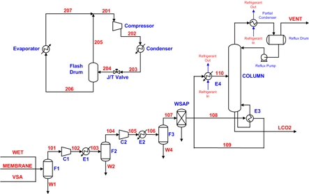
Schematic diagram for an overall process to obtain liquefied CO2 using cryogenic distillation process with vapor recompression refrigerant cycle
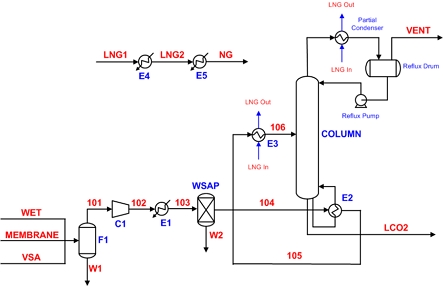
Schematic diagram for an overall process to obtain liquefied CO2 using cryogenic distillation process with the cold heat of LNG
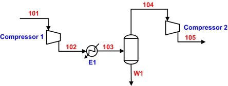
중간에 냉각기를 가지는 이단 압축공정을 이용해서 이산화탄소를 25 bar까지 가압한 다음에 후단 냉각기를 이용해서 냉각수가 냉각시킬 수 있는 온도인 45℃까지 냉각시킨 후에 몇 가지 냉매를 이용한 증기 재압축 냉동 사이클을 이용해서 -30℃까지 냉각시켜서 액화시킨다. 이단 압축공정의 경우에 입구와 출구의 압력이 정해져 있으므로 첫 번째 압축기 후단의 압력 변화에 따라서 총 소요 동력이 변화하게 된다. 이번 연구에서는 총 소요 동력을 최소화시켜 주는 최적의 첫 번째 압축기 후단의 압력을 전산 모사를 통해서 결정하였다. Fig. 3에 이단 압축공정에 대한 개요도를 나타내었다
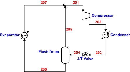
Fig. 4에 냉매를 활용한 증기 재압축 냉동 사이클에 대한 개요도를 나타내었다. 냉매로써 혼합 냉매인 R404a와 순수 성분 냉매들인 암모니아, 프로판 및 프로필렌을 사용하여 이산화탄소를 -30℃까지 냉각시켜서 액화시키는 공정에 대해서 냉동 사이클의 소요 동력과 냉매 증발기의 전열 면적을 냉매별로 상호 비교하였다. Fig. 4에 의하면 대기압보다 조금 높은 압력 조건에서 이슬점 상태의 냉매는 압축기에 의해 높은 압력으로 가압된 다음 냉매 응축기에서 냉각수에 의해 45℃까지 냉각된 후 액화된다. 냉매 압축기 후단의 압력은 주어진 냉매의 45℃에서의 기포점 압력과 동일하다. 응축된 냉매는 줄-톰슨 팽창밸브에 의해 대기압보다 약간 높은 압력까지 팽창된다7). 팽창된 후에도 증발도 같이 일어나게 되는데 냉매가 증발하면서 잠열을 빼앗아 가므로 냉매의 온도는 급격히 떨어지게 된다. 이때 온도가 바로 주어진 냉매의 공급 온도가 된다.
Fig. 5에는 LNG 냉열을 활용하여 이산화탄소를 냉각 및 액화시키는 공정에 대한 개요도를 나타내었다. LNG 냉열을 이용해서 이산화탄소를 액화시키기 위해서 단일 압축을 이용해서 8 bar까지 가압한 후에 이산화탄소의 어는점보다 약간 높은 -50℃까지 냉각시킨 후에 액화시킨다.
이단 압축공정과 냉동 사이클을 적용한 경우에 소요되는 동력을 추산하고, 1단 압축과 LNG 냉열을 사용하는 경우에 절감되는 소요 동력을 추산하여 상호 비교하였다. 각각의 전산 모사 과정은 AVEVA 사의 Aspen Plus V12.1 전산 모사기(AVEVA, Cambridge, UK)를 사용하여 전산 모사 작업을 수행하였다. 본 연구에서 사용한 열역학 모델식은 포집 공정별 혼합 프로세스 및 중간에 냉각기를 가지는 이단 압축공정 그리고 수분 제거를 위한 드라이어 공정과 심냉 증류 공정에 대해서는 Soave-Redlich-Kwong (SRK) 상태 방정식을 사용하였고, 냉동 사이클 공정에는 REFPROP 모델식을 사용하였다8). 또한 단일 성분의 온도에 따른 증기압을 좀 더 잘 추산하기 위해서 Pitzer의 이심 인자를 사용하는 대신에 Twu가 제안한 새로운 alpha function을 적용하였다9).
2. 열역학 이론
2.1 이산화탄소 액화 공정의 전산 모사에 적합한 열역학 모델식의 선정
다성분계 혼합물의 증기-액 공존상을 포함하는 상평형에 대한 열역학적인 해석은 증기상과 액상에서 각 성분의 퓨개시티가 같다는 식 (1)의 가정에서부터 출발한다.
| (1) |
혼합물의 증기-액 상평형을 추산하는 접근 방법은 증기상과 액상의 퓨개시티를 모두 상태 방정식 모델식을 이용한 one model approach와 증기상의 퓨개시티는 상태 방정식 모델식을, 액상의 퓨개시티는 활동도계수 모델식을 이용한 two model approach가 있다10). 식 (2)와 식 (3)에는 각 상에서 임의의 성분에 대한 퓨개시티 계수 표현식을 나타내었다.
| (2) |
| (3) |
식 (2)와 식 (3)을 연립하면 식 (4)와 같이 쓸 수 있으며, 이를 one model approach라 한다.
| (4) |
한편 식 (5)에는 상태 방정식 모델식에 적용한 혼합물 중의 성분 i의 퓨개시티 계수 표현식을 나타내었다.
| (5) |
그리고 액상의 퓨개시티 계수는 다음의 식 (6)과 같이 쓸 수 있다.
| (6) |
2.2 순수 성분의 온도에 따른 증기압을 잘 추산하기 위한 Alpha function
SRK 상태 방정식에서 Pitzer가 최초로 제안한 이심 인자의 함수로 표현한 alpha function은 환산 온도가 증가하면 다시 증가하는 함수로 탄화수소 성분 이외 성분들에 대한 증기압 추산에는 적합하지 않다. 이러한 단점을 보완하기 위해 본 연구에서는 성분 각각에 대해서 다른 계수를 사용하는 Twu 등9)이 제안한 새로운 alpha function을 사용하였으며 그 표현식은 다음의 식 (7)과 같이 나타낼 수 있다.
| (7) |
식 (7)에서 Tr은 순수 성분의 환산 온도이며 C1, C2 및 C3는 성분마다 다르게 지정된 순수 성분의 온도에 따른 증기압을 잘 추산하기 위한 매개변수들이다. 본 연구에서 사용한 성분들에 대한 Twu 모델식의 계수를 Table 2에 나타내었다.
3. 전산 모사
3.1 증기 재압축 냉동 사이클의 냉매 종류 및 물리적 특성
Table 4에 본 연구에 사용된 냉매들의 물리적 특성에 대해 정리하여 나타내었다
3.2 이단 압축공정의 최적화
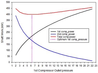
Fig. 6에는 두 기의 압축기 소요 동력의 합이 최소가 되는 첫 번째 압축기 후단의 압력을 결정하기 위한, 첫 번째 압축기 후단 압력의 함수로 첫 번째와 두 번째 압축기의 소요 동력 및 총 소요 동력의 변화를 그래프로 나타내었다. Fig. 6에서 볼 수 있듯이 첫 번째 압축기 후단의 압력이 증가할수록 첫 번째 압축기의 소요 동력은 증가하고 반대로 두 번째 압축기의 소요 동력은 감소한다. 두 개의 압축기의 합이 최소가 되는 첫 번째 압축기 후단의 압력은 6.24 bar로 총 소요 동력은 398 kW가 됨을 알 수 있다.
한편 Table 5에 이단 압축공정 모사 결과를 나타내었다. 두 개의 압축기의 소요 동력이 최소가 되는 1단 압축기의 소요 동력은 218.6 kW이며 두 번째 압축기의 소요 동력은 179.4kW이다.
3.3 냉동 사이클 전산 모사
Table 6에는 본 연구에 적용된 몇 가지 냉매를 이용한 냉동 사이클 전산 모사 결과를 나타내었다. 냉동 사이클 압축기 전단의 온도는 냉매의 끓는점보다 3℃ 높은 온도로 설정하였으며 증발기의 duty는 심냉 증류탑 condenser duty와 E4 cooler duty의 합과 같게 만들기 위해 압축기 전단에 흐르는 냉매의 유량으로 조정하였다. 본 연구에 사용한 냉매 중에서 압축기 소요 동력이 가장 작은 냉매는 R717 냉매로 246.2 kW이며 압축기 소요 동력이 가장 큰 냉매는 혼합 냉매인 R404a로 437.4 kW이다.
3.4 냉동 사이클 증발기의 전열 면적
Table 7에 냉매별 냉동 사이클 증발기의 크기와 길이를 결정할 때 사용하는 대수 평균 온도 차이를 나타내었다. 이를 살펴보면 암모니아 냉매를 사용하였을 경우 가장 작은 것을 알 수 있다. 동일한 총괄 열전달 계수를 가정하고 전열 면적을 계산하면 전열 면적이 가장 적은 냉매는 R1270으로 4,380 m2이며 가장 큰 냉매는 R717로 17,614 m2임을 알 수 있었다.
3.5 LNG 냉열을 활용한 CO2 액화 전산 모사
Table 8에 LNG 냉열을 활용한 CO2 액화공정의 전산 모사 결과를 나타내었다. CO2 액화공정에 있어 LNG 냉열을 이용하면 냉매를 사용하는 냉동 사이클의 압축기 및 CO2 액화공정의 이단 압축을 위한 두 번째 압축기의 소요 동력을 절감할 수 있다. Table 9와 Table 10에 LNG 냉열을 활용하는 경우와 냉동 사이클을 이용하는 경우의 소요 동력 비용을 정리하였다. 동일한 기준으로 소요 동력 비용 계산을 위해 일 24시간, 1달 30일 가동 조건으로 계산하였으며 kwh 당 전력비는 산업용 고압 A 중간 부하의 봄, 가을철 전력 요금을 기준으로 하였다.
4. 결 론
첫째, LNG 냉열을 이용할 경우 이단 압축 대신에 단일 압축도 가능하며 압축기 소요 동력 및 냉동 사이클의 압축기 소요 동력을 줄일 수 있어 프로판 냉매를 사용하는 냉동 사이클 대비 월 3천 5백만 원의 에너지 비용 절감 효과를 가져올 수 있었다.
둘째, 연구에 사용된 냉매 중 암모니아 냉매의 냉동 사이클 압축기 소요 동력이 246 kW로 가장 적었으나, 냉매 증발기의 전열 면적은 다른 냉매에 비해 3배가량 크게 추산되는 것을 알 수 있었다.
셋째, 중간에 냉각기를 가지는 이단 압축 후에 냉매를 이용하는 증기 재압축 냉동 사이클을 사용하여 이산화탄소를 액화시키는 대신에 LNG 냉열을 이산화탄소 액화 공정에 적용할 경우 총 압축기 소요 동력을 55-69%가량 절감할 수 있었다
Acknowledgments
본 연구는 2023년도 정부(과학기술정보통신부)의 재원으로 한국연구재단-CCU3050 사업의 지원을 받아 수행된 연구임(No.2022M3J2A1063788).
References
- K. T. Kim, J. S. Ahn, Y. A, Lee, and J. Y. Choi, “CCUS In-depth investment analysis report”, Korea Institute of Energy Research, 2021. Retrieved from https://www.kier.re.kr/UploadFiles/tpp/energy/16366126893490.pdf, .
-
Y. Le Moullec, T. Neveux, K. Makhloufi, D. Roizard, M. Kanniche, and E. Favre, "Development of a CO2 capture process based on ammonia solvent and a dedicated composite hollow fibre membrane contactor", Energy Procedia, Vol. 63, 2014, pp. 651-658.
[https://doi.org/10.1016/j.egypro.2014.11.072]

-
R. Bouma, F. Vercauteren, P. van Os, E. Goetheer, D. Berstad, and R. Anantharaman, "Membrane-assisted CO2 liquefaction: performance modelling of CO2 capture from flue gas in cement production", Energy Procedia, Vol. 114, 2017, pp. 72-80.
[https://doi.org/10.1016/j.egypro.2017.03.1149]

-
Z. Rui, J. B. James, A. Kasik, and Y. S. Lin, "Metal-organic framework membrane process for high purity CO2 production", AIChE Journal, Vol. 62, No. 11, 2016, pp. 3836-3841.
[https://doi.org/10.1002/aic.15367]

-
J. C. L. Y. Fong, C. J. Anderson, G. Xiao, P. A. Webley, and A. F. A. Hoadley, "Multi-objective optimisation of a hybrid vacuum swing adsorption and low-temperature post-combustion CO2 capture", Journal of Cleaner Production, Vol. 111, Pt. A, 2016, pp. 193-203.
[https://doi.org/10.1016/j.jclepro.2015.08.033]

-
S. Yang, U. Lee, Y. Lim, Y. S. Jeong, J. Kim, C. Lee, and C. Han, "Process design and cost estimation of carbon dioxide compression and liquefaction for transportation", Korean Chemical Engineering Research, Vol. 50, No. 6, 2012, pp. 988-993.
[https://doi.org/10.9713/kcer.2012.50.6.988]

-
J. Cho, "A study on the power saving with the use of LNG cold heat in a cascade refrigeration cycle using methane, ethylene and propylene as refrigerants", Journal of Hydrogen and New Energy, Vol. 31, No. 3, 2020, pp. 302-306.
[https://doi.org/10.7316/KHNES.2020.31.3.302]

- J. M. Smith, H. C. Van Ness, M. M. Abbott, and M. T. Swihart, “Introduction to chemical engineering thermodynamics”, 8th ed, McGraw Hill, 2018, USA, pp. 327-343.
-
C. H. Twu, D. Bluck, J. R. Cunningham, and J. E. Coon, “A cubic equation of state with a new alpha function and a new mixing rule”, Fluid Phase Equilibria, Vol. 69, 1991, pp. 33-50.
[https://doi.org/10.1016/0378-3812(91)90024-2]

- J. Cho, K. Cho, D. Kim, Y. Lee, and S. Hong, "Estimation of physical properties of natural gas using cubic equations of state", Journal of the Korean Institute of Gas, Vol. 10, No. 4, 2006, pp. 6-10. Retrieved from https://scienceon.kisti.re.kr/commons/util/originalView.do?cn=JAKO200606141824634&oCn=JAKO200606141824634&dbt=JAKO&journal=NJOU00291946, .

