1D Kinetics Model of NH3-Fed Solid Oxide Fuel Cell
2022 The Korean Hydrogen and New Energy Society. All rights reserved.
Abstract
Cracking ammonia inside solid oxide fuel cell (SOFC) stack is a compact and simple way. To prevent sharp temperature fluctuation and increase cell efficiency, the decomposition reaction should be spread on whole cell area. This leading to a question that, how does anode thickness affect the conversion rate of ammonia and the cell voltage? Since the 0D model of SOFC is useful for system level simulation, how accurate is it to use equilibrium solver for internal ammonia cracking reaction? The 1D model of ammonia fed SOFC was used to simulate the diffusion and reaction of ammonia inside the anode electrode, then the partial pressure of hydrogen and steam at triple phase boundary was used for cell voltage calculation. The result shows that, the ammonia conversion rate increases and reaches saturated value as anode thickness increase, and the saturated thickness is bigger for lower operating temperature. The similar cell voltage between 1D and 0D models can be reached with NH3 conversion rate above 90%. The 0D model and 1D model of SOFC showed similar conversion rate at temperature over 750℃.
Keywords:
Kinetic model, SOFC, 0D model, 1D model, Ammonia conversion키워드:
반응 모델, 고체산화물 연료전지, 0차원 모델, 1차원 모델, 암모니아 전환1. Introduction
To mitigate climate change, the world energy is transformed into renewable energy, such as solar power and wind power1). The renewable energy can be transported directly to the customers or through a form of hydrogen or its carriers2). The hydrogen carriers are getting attention because hydrogen has low volumetric energy density and difficult to be stored. For example, liquid hydrogen has volumetric energy density of 8.49 MJ/l, but required to be kept at a very low temperature of -253℃.
There are several types of hydrogen carriers with different development level. For high volumetric energy density, using metal hydrides could be a promising approach. However, so far, they are suffering from low gravimetric energy density, since metals are normally heavy3,4). For relatively high volumetric and high gravimetric energy density, ammonia is a good option. Ammonia has energy density of 12.7 MJ/l, and 18.7 MJ/kg, and it can be stored stably in liquid state at 11 bar and 25℃5).
Ammonia can be made from H2 and N2 using renewable energy with very little carbon footprint. Firstly, hydrogen is produced by electrolysis using electricity from solar farm or wind farm. And nitrogen can be extracted from air by liquefaction using renewable energy. Ammonia has been being produced using Haber-Bosch process since earlier than 100 years ago. However, scientists are still working on finding new ways with lower required pressure and temperature6).
Though ammonia was first mass produced more than 100 years ago, they have been mostly for agricultural applications7). To be a good energy carrier, ammonia should be used effectively to generate electricity. So far fuel cells system showed the highest electrical efficiency among hydrogen-fueled power generation technologies. Ammonia needs to decompose to produce H2 and then be fed to fuel cells. The decomposition process is an endothermic reaction, so the overall system efficiency can be improved if heat generated from fuel cells is used. Owing to high operating temperature, solid oxide fuel cell can provide high temperature for internal cracking of ammonia fuel.
To analyze whole fuel cell system, a 0D model of fuel cell stack is normally used8). The 0D model is very quick to compute and quite accurate when there is only electrochemical reaction occurs inside fuel cell. However, when there is direct internal decomposition of NH3 occurs, the simple 0D model might lose its accuracy. In that case 1D model will be more reliable, which considers NH3 decomposition reaction takes place inside the anode electrode. Nonetheless, the computation cost of 1D model is not acceptable for system modeling.
So far, the 0D model approach typically considers all decomposition or reforming reactions finished inside the fuel channel, and the fuel composition at triple phase boundary will be estimated using multi-components diffusion models. The 1D model approach, in other hand, considers the decomposition reaction happens only in anode electrode. The anode is discretized along its thickness direction and the material composition in whole anode field are estimated using iteration calculation method. In this paper, the results of 0D and 1D models are compared, and then the applicable condition where 0D model and 1D model show similar output will be suggested.
2. Mathematic model of solid oxide fuel cell (SOFC)
2.1 Assumptions
For modeling of SOFC, the following assumptions were used:
- · The temperature of SOFC cell is uniformly distributed.
- · The material composition of fuel and air channel are uniform.
- · The Ohmic loss on interconnector and electrodes are negligible.
- · SOFC is modeled in steady state.
- · In 0D model, the equilibrium reaction occurs inside the fuel channel
- · In 1D model, the cracking reaction occurs inside the fuel electrode
2.2. Electrochemical model
The SOFC cell voltage was modeled considering three types of voltage loss: Ohmic loss, activation loss, and concentration loss, as following:
U=Urev – Uact – UOhm – Ucon
where Nernst voltage was calculated:
| (1) |
- where:
- ΔG : Gibbs free energy change of electrochemical reaction at temperature T
- R : Universal gas constant
- F : Faraday constant
- yi : molar fraction of the substance i
- p : pressure of anode channel
Activation loss was calculated based on molar fraction of substance at the triple phase boundary and current density:
| (2) |
- Where j0 is exchange current density:
| (3) |
| (4) |
where γa and γf are fitting parameters. EO2 and EH2 are activation energy of cathode and anode electrodes, respectively.
Ohmic loss is calculated depending on the thickness of electrolyte, current density, and temperature of SOFC:
| (5) |
Concentration loss will become significant at high current density, due to the slow diffusion speed compared to reaction rate.
| (6) |
- where:
- yO2tpb : molar fraction of O2 at triple phase boundary
- yH2tpb : molar fraction of H2 at triple phase boundary
From here, the 0D and 1D model will have different method of calculating molar fractions at triple phase boundary (TPB).
2.3. 0D model
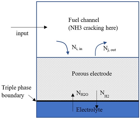
The ammonia decomposition reaction was assumed an equilibrium process that takes place at the fuel channel, as shown in Fig. 1:
NH3 → 0.5N2 + 1.5H2
The reaction constant was used as following9):
| (7) |
Set the reacted rate of ammonia is aNH3 (mol/s) and total inlet molar flow is n. Based on current density and dimension of the SOFC stack, the reaction rate of H2 (aH2) can be estimated.
| (8) |
| (9) |
With given molar flow rate and composition of inlet fuel, the equation (1) can be solved for XNH3. And then the equilibrium composition of fuel channel can be calculated.
The molar fraction of all substances at TPB was calculated using dusty gas diffusion model.
| (10) |
| (11) |
| (12) |
| (13) |
| (14) |
- where:
- d (m) : electrode thickness
- Mi (g/mol) : molar weight of substance i
- i, j : H2,H2O
- m : number of substances
- k : substance index
2.4. 1D model
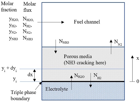
The anode electrode was assumed consist of n layers, each layer has thickness of dx=da/n (da=anode electrode thickness), as shown in Fig. 2. The molar flux of each substance Ni [mol/(m2s)] was calculated following Dusty gas model:
| (15) |
| (16) |
where P and k are pressure and the layer number. Therefore, dyi,k=yi,k–yi,k-1 and dPk=Pk-Pk-1. B0 is permeability of porous electrode10), µ is viscosity of the mixture. Deff is effective diffusion coefficient.
There are m unknowns (yi) and m equations (15) for each layer. The molar flux Ni is calculated from Ni-1, which originated from boundary condition:
Ni=Ni-1 + dNi
The dNi was calculated from reaction rate r of NH3 in the porous electrode:
| (17) |
where E and PNH3 are activation energy and partial pressure of NH3. A is pre-exponential term, which is fitting coefficient. Accordingly, we have:
dNNH3=-rdx, dNH2=1.5rdx, dNN2=0.5rdx
And boundary condition at triple phase boundary (x=0) is:
NNH3=0, NH2=-J/2F, NN2=0
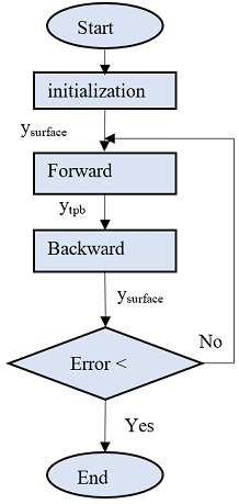
The molar fraction of all substance at whole anode electrode was calculated subsequently from triple phase boundary to the surface of the electrode and then backward from the surface to the triple phase boundary until all result values are close enough. The calculation flow is shown in Fig. 3. Firstly, the molar fraction of all substances was initialized at surface of electrode. Using forward calculation, the composition, molar flux, and pressure at each discretized layer were calculated one by one until the values at TPB were reached. And then by using the calculated condition at TPB and electrochemical reaction at the TPB, the molar fluxes were updated. And then the backward calculation was used to calculate the new composition at surface of the electrode. The new calculated values will be compared to the old ones. If the error is below requirement the loop was stopped.
3. Results and discussion
3.1 Model validation
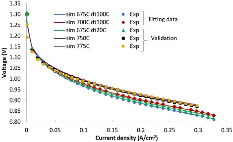
Electrochemical and 0D model was validated with experimental data of N2/H2 fed SOFC11). Information of SOFC cell and fitted parameters are listed in Table 1. The experimental data at 675°C and 700°C were used for fitting model parameters. The data on the other temperature were used for validation. As shown in Fig. 4, the 0D model well agrees with experimental data.
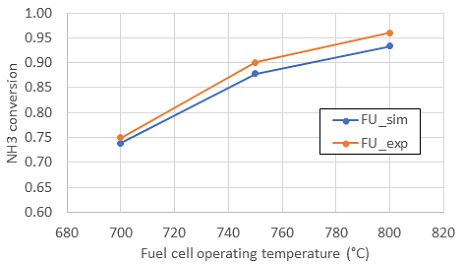
The electrochemistry model was validated with experiment without cracking reaction. The purpose of the current study is comparing the conversion rate and composition at TPB between 0D and 1D model. So conversion rate in experiment is enough to validate 1D kinetics model. 1D model was validated by comparing simulated conversion rate of NH3 with that in experiment of reference12), as shown in Fig. 5. The simulated result showed error max error of 2.7% compared to experiment.
Fitted parameters are as following: A=8e11; E=2.5e5. Fuel composition along anode electrode thickness in case of no current and current density of 3,000 A/m2 are illustrated in Figs. 6, 7. The forward calculation results well match with backward calculation results. As current density equal 0, all molar flux become zero at the TPB. The positive molar flux means the substances go from surface of anode to the TPB. Because NH3 cracking reaction induces generation of molar flow, the pressure near TPB is higher than at the surface of anode.
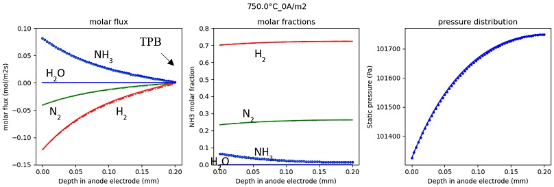
Molar flux, molar fraction, and pressure in anode electrode at 0 current density (dotted lines are forward calculation result, solid lines are backward calculation results).
3.2. Effect of electrode thickness on NH3 conversion rate
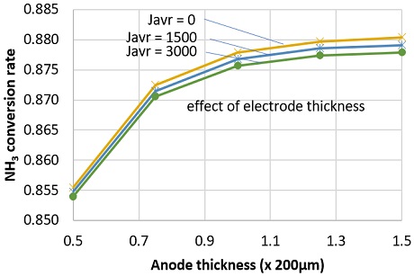
NH3 conversion rate decreased at higher current density. This might be attributed to the increasing of diffusion flow of water at high current density. Though hydrogen was consumed faster at high current density, the effect on NH3 diffusion flow is smaller than that of water. As shown in Fig. 8, at anode thickness of 200 µm, NH3 conversion rate slightly decreased from 0.8779 to 0.8757 as current density increased from 0 to 3,000 A/m2. Fig. 8 also indicates that, the NH3 conversion rate slowly increase at thicker anode electrode. This could be attributed to the slow diffusion flux of NH3 at thicker anode electrode.
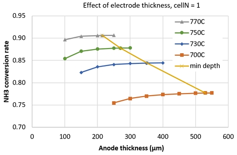
An investigation of NH3 conversion rate at different operating temperature showed that, the saturated thickness (where the NH3 conversion rate increase less than 1%/50µm) increased with decreasing operating temperature, as shown in Fig. 9. Here, min depth line is for connecting the saturated thickness points. This means, at lower temperature, we need thicker anode electrode to significantly decompose NH3. The min depth line connects the saturated points.
3.3. Comparison between 0D model and 1D model
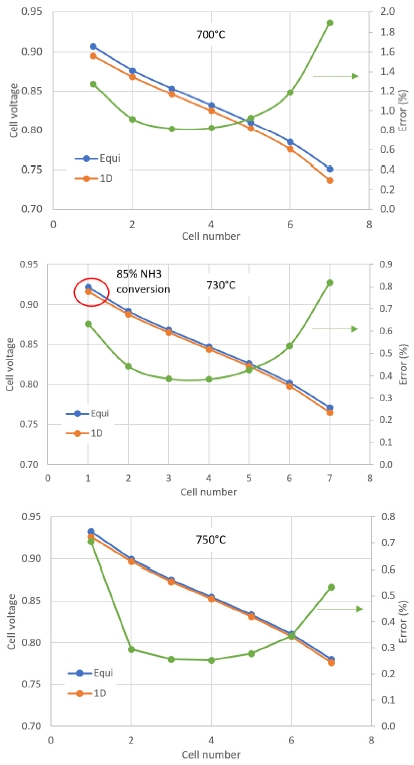
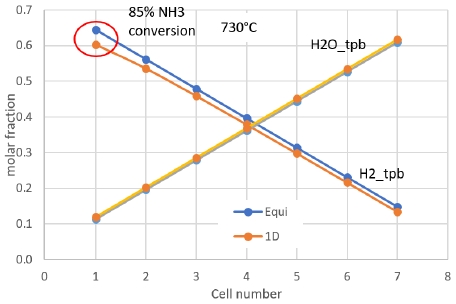
Calculation results from 0D and 1D models were compared in molar fraction output and stack voltage at different cell number. Cell voltage at operating temperature from 730℃ and above showed error less than 1% between 0D and 1D model. Though the molar faction of H2 at anode off-gas showed 6.7% difference. Moreover, at 730℃, 1 cell, the NH3 conversion rate was only 85%, as shown in Fig. 10. This might be caused by dominant effect of water molar fraction in the Nernst Voltage. At more cell number, the molar fraction of H2 in 0D and 1D models showed closer values as shown in Fig. 11.
4. Conclusion
SOFC stack model using 0D and 1D approaches were investigated. The 0D model used equilibrium reaction assumption to find fuel composition at the channel and then applied Dusty gas model to find composition of all substances at triple phase boundary. The 1D model used reaction kinetic of NH3 cracking at porous anode electrode. We found that:
- · The NH3 decomposition rate quickly get saturated as anode thickness increases. As operating temperature increase, the effective thickness decreases.
- · The similar cell voltage doesn’t mean the composition of output flows are similar.
- · As conversion of NH3 is higher than 90%, 0D and 1D model results in similar cell voltage (error below 1%).
- · At cell temperature of 750℃ and above, the conversion rate of NH3 and cell voltage are similar for both 0D and 1D kinetics model. So, it is acceptable to consider equilibrium reaction occur only in the channel.
- · At temperature lower than 750℃, it is necessary to simulate the NH3 fed SOFC using 1D kinetic model due to large different in molar fraction of anode off-gas flow.
Acknowledgments
This work was supported by the Korea Institute of Energy Technology Evaluation and Planning (KETEP) and the Ministry of Trade, Industry & Energy (MOTIE) of the Republic of Korea (No. 20213030040110). This research was also supported by a grant of the Research Program funded by the Korea Institute of Machinery and Materials (project name: Development of an ammonia fuel cell stack and system, grant number: NK237G).
References
- IRENA, “Energy transition 2020”, IRENA, 2020. Retrieved from https://www.irena.org/energytransition#:~:text=The%20energy%20transition%20is%20a,emissions%20to%20limit%20climate%20change, .
- Air Liquide S.A., A., Anglo American plc, BMW Group, Daimler AG, Engie S.A., Honda Motor Co. Ltd, Hyundai Motor Company, Kawasaki Heavy Industries Ltd., Royal Dutch Shell, The Linde Group, and Total S.A., Toyota Motor Corporation, "How hydrogen empowers the energy transition", 2017, Hydrogen Council. Retrieved from https://www.aeh2.org/images/stories/AEH2/Docs_Externos/20170109-hydrogen-council-vision-document.pdf, .
-
M. V. Lototskyy, V. A. Yartys, B. G. Pollet, and R. C. Bowman Jr, “Metal hydride hydrogen compressors: a review”, Int. J. Hydrogen Energy, Vol. 39, No. 11, 2014, pp. 5818-5851.
[https://doi.org/10.1016/j.ijhydene.2014.01.158]

-
N. A. A. Rusman and M. Dahari, “A review on the current progress of metal hydrides material for solid-state hydrogen storage applications”, Int. J. Hydrogen Energy, Vol. 41, No. 28, 2016, pp. 12108-12126.
[https://doi.org/10.1016/j.ijhydene.2016.05.244]

-
J. S. Lee, A. Cherif, H. J. Yoon, S. K. Seo, J. E. Bae, H. J. Shin, C. Lee, H. Kwon, and C. J. Lee, “Large-scale overseas transportation of hydrogen: comparative techno-economic and environmental investigation”, Renewable and Sustainable Energy Reviews, Vol. 165, 2022, pp. 112556.
[https://doi.org/10.1016/j.rser.2022.112556]

-
S. Ghavam, M. Vahdati, I. A. Grant Wilson, and P. Styring, “Sustainable ammonia production processes”, Front. Energy Res., 2021.
[https://doi.org/10.3389/fenrg.2021.580808]

- IEA, “Ammonia technology roadmap”, IEA, 2021. Retrieved from https://www.iea.org/reports/ammonia-technology-roadmap, .
-
S. A. Hajimolana, M. A. Hussain, W. M. A. Wan Daud, M. Soroush, and A. Shamiria, “Mathematical modeling of solid oxide fuel cells: a review”, Renewable and Sustainable Energy Reviews, Vol. 15, No. 4, 2011, pp. 1893-1917.
[https://doi.org/10.1016/j.rser.2010.12.011]

-
M. E. E. Abashar, “Ultra-clean hydrogen production by ammonia decomposition”, Journal of King Saud University - Engineering Sciences, Vol. 30, No. 1, 2018, pp. 2-11.
[https://doi.org/10.1016/j.jksues.2016.01.002]

-
E. S. Hecht, G. K. Gupta, H. Zhu, A. M. Dean, R. J. Kee, L. Maier, and O. Deutschmann, “Methane reforming kinetics within a Ni-YSZ SOFC anode support”, Applied Catalysis A: General, Vol. 295, No.1 , 2005, pp. 40-51.
[https://doi.org/10.1016/j.apcata.2005.08.003]

-
T. Q. Quach, V. T. Giap, D. K. Lee, I. T. Pineda, and K. Y. Ahn, “Parametric study of a high-performance ammonia-fed SOFC standalone system”, Journal of Mechanical Science and Technology, Vol. 36, No. 6, 2022, pp. 3193-3201.
[https://doi.org/10.1007/s12206-022-0550-7]

-
G. Cinti, G. Discepoli, E. Sisani, and U. Desideri, “SOFC operating with ammonia: stack test and system analysis”, Int. J. Hydrogen Energy, Vol. 41, No. 31, 2016, pp. 13583-13590.
[https://doi.org/10.1016/j.ijhydene.2016.06.070]

