수소 안전밸브용 역화방지기의 성능 평가에 대한 수치해석 연구
2022 The Korean Hydrogen and New Energy Society. All rights reserved.
Abstract
Hydrogen is one of the energy carriers and has high energy efficiency relative to mass. It is an eco-friendly fuel that makes only water (H2O) as a by-product after use. In order to use hydrogen conveniently and safely, development of production, storage and transfer technologies is required and attempts are being made to apply hydrogen as an energy source in various fields through the development of the technology. For transporting and storing hydrogen include high-pressure hydrogen gas storage, a type of storage technologies consist of cryogenic hydrogen liquid storage, hydrogen storage alloy, chemical storage by adsorbents and high-pressure hydrogen storage containers have been developed in a total of four stages. The biggest issue in charging high-pressure hydrogen gas which is a combustible gas is safety and the backfire prevention device is that prevents external flames from entering the tank and prevents explosion and is essential to use hydrogen safely. This study conducted a numerical analysis to analyze the performance of suppressing flame propagation of 2, 3 inch flame arrestor. As a result, it is determined that, where the flame arrestor is attached, the temperature would be lowered below the temperature of spontaneous combustion of hydrogen to suppress flame propagation.
Keywords:
Hydrogen, Safety valve, Flame arrestor, Computational fluid dynamics(CFD), Detonation키워드:
수소, 안전밸브, 화염방지기, 전산유체역학, 폭발1. 서 론
수소는 에너지 캐리어(energy carrier) 중 하나로 질량 대비 에너지 효율이 높으며(석유 대비 단위 질량당 발열량 약 3배) 사용 후 부산물로 물(H2O)만 배출되는 친환경적 연료이다. 따라서 기존의 석유, 석탄과 같은 화석연료1-5)를 대체하고 지구온난화 문제를 해결할 미래에너지로 주목받고 있다. 또한 수소는 지역적 편중이 없는 에너지 자원6,7)으로 지구상 어디에서나 여러 가지 물질 속에 포함되어 존재하며 특히 물을 전기 분해하여 얻을 수 있으므로 무한한 자원으로 평가받고 있다. 이처럼 장점이 많은 수소를 편리하고 안전하게 활용하기 위해서는 생산, 저장, 이송 기술의 발전이 필요하며 이러한 기술의 발전을 통해 다양한 방면에서 수소를 에너지원으로 적용하기 위한 시도를 하고 있다8).
수소는 에너지의 저장 측면에서 활용의 가치가 크다. 온실가스에 의한 환경문제9-11)로 재생에너지 발전의 비중이 확대되고 있는 시점에서 생산된 에너지의 저장을 위해 발전량이 많을 때 남는 전기를 이용한 수전해 방식으로 수소를 생산하고 저장하여 재생에너지의 단점인 기후 영향에 의한 에너지 부족에 대비할 수 있다.
수소를 수송, 보관하기 위한 저장 기술로는 고압의 수소 기체 저장법, 극저온의 수소 액체 저장법, 수소 저장 합금 등 고체 저장법, 흡착물질에 의한 화학적 저장법 등의 기술이 연구되고 있다7).
특히, 기술 등의 제약에 따라 현재까지 보편적으로 수소를 저장하는 방법은 고압 수소 기체 저장법 이였다. 고압 수소 저장 용기는 이를 구성하는 재료 및 복합재료 강화 방법의 발전에 따라 Type I, II, III, & IV로 총 4단계의 발전이 이루어졌다12-16). 가연성 기체인 고압의 수소가스 충전에 있어 최대 이슈는 안전이다. 고압저장용기에서 압력배출 안전밸브는 육상 플랜트의 케미칼 또는 수소 탱크의 루프나 배관의 끝단에 설치되어 탱크 내부의 압력을 일정하게 유지시켜주며 역화방지장치는 외부의 화염이 탱크 내부로 침입하는 것을 차단하여 폭발 사고를 방지하는 장치이다.
역화방지장치는 가연성 가스의 유로부에 금속망을 설치하여 고온의 화염이 좁은 간격의 벽면에 접촉, 열전도에 의해 급속히 온도를 감소시켜 작동유체의 자발화온도 이하로 유지시켜 화염이 전파되는 것을 방지하는 장치이며, 일반적으로 element, body, 격판, element ring으로 구성되어 있다17). 일반적으로 화염방지기는 석유 화학 및 천연가스 산업에 사용되어 왔고 따라서 기존 산업현장에 대한 연구가 진행되어 왔다18-21). 하지만 수소 적용 역화방지기에 대한 연구는 미미하다.
따라서 본 연구에서는 수소 역화방지장치에 대한 수치해석적 연구를 통해 화염방지장치의 성능을 분석하고 다공성매질에 대한 수치해석 모사를 검토하고자 한다.
2. 수치해석 방법
2.1 지배방정식
본 연구에서 화염역화방지기의 성능분석을 위해 상용프로그램인 ANSYS Fluent (Ansys, Inc., Canonsburg, PA, USA)를 사용하였으며, 지배방정식은 다음과 같다22).
-Conservation of mass
| (1) |
-Conservation of momentum
| (2) |
여기서,
| (3) |
이다.
-Conservation of mass of species
| (4) |
-Conservation of energy
| (5) |
각각의 수식에서 ui는 속도, ρ는 밀도, p는 압력을 나타내며, τi, j는 점성응력, Yα는 종 α의 질량분율, D는 화산계수를 나타낸다.
2.2 수치해석 방법
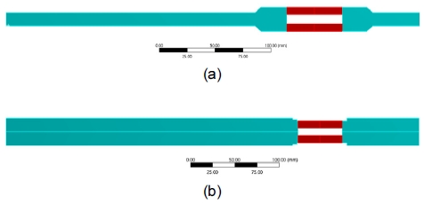
화염역화방지기 유동해석을 위해 Fig. 1과 같이 해석에 적용되는 역화방지기를 3D 모델링 하였다. 본 해석의 목적은 역화방지기 부분을 통과하는 화염이 연소되는 기체 혼합물에서 발생하는 열을 역화방지기가 흡수, 발산시켜 반대쪽(protected side)에 있는 가연성 기체가 자연 발화 온도에 오르지 않도록 연소 온도를 감소시키는 것을 확인하는 것이므로 Fig. 2(a)의 기존 모델의 element부를, Fig. 2 (b), (c)와 같이 역화방지기의 element부를 porous로 처리하여 해석을 진행하였다. Fluent에서 다공성 매질에 적용된 수식은 다음과 같으며,
| (6) |
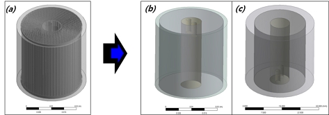
Modified model of element of flame arrestor to make porous zone. (a) Element model. (b) 2 inch porous model. (c) 3 inch porous model.
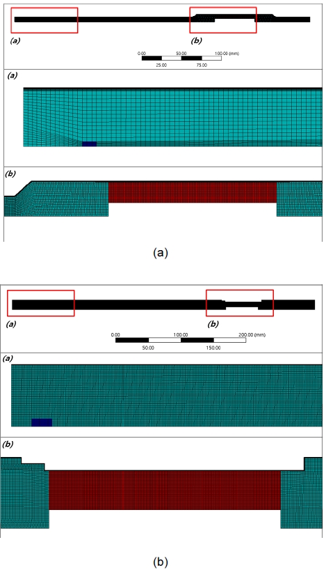
여기서 S는 운동량 방정식에 대한 생성항이며, α는 삼투성, C2는 관성저항을 나타낸다. 따라서 수정된 모델링 2가지를 적용하여 내부 유동장을 형성하였으며 해석 모델은 축대칭(axisymmetric)으로 설정하였다. 자세한 유동장 형태는 Fig. 3과 같고 여기서 붉은 범위의 영역은 역화방지기 porous zone을 나타내며, 그 외의 범위는 일반 유동장을 나타낸다. Fig. 4는 유동장의 생성 격자를 나타낸다.
3. 결과 및 고찰
3.1 Porous zone 해석
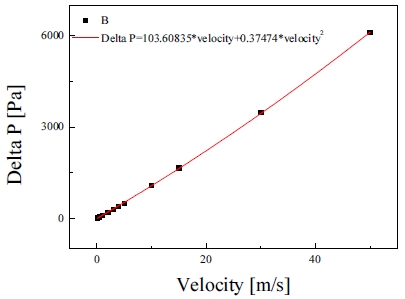
설정된 porous zone23,24)을 해석하기 위해서는 Darcy’s law/power law model에 기초한 porous model을 적용하여 유동에 따른 압력 강하를 적절히 설정하여야 한다. 따라서 element의 미소 부분을 모델링하여 입구 유동 속도 범위 0-50 m/s 구간에서 porous zone의 압력강하 데이터를 확보하였으며 이는 Fig. 5와 같다. 그래프에서 도출된 수식에서 속도 항의 1차, 2차 형태로 데이터의 근사 곡선을 도출하였으며 이를 수식 (6)으로 분석하여 각각의 저항 계수값을 도출하였다. Darcy’s Law 화염역화방지기 유동해석을 위해 해석에 적용되는 역화방지기는 앞서 제시된 Fig. 3의 3D 모델링을 활용하였으며, porous zone을 통과하는 유체와 porous zone의 열교환은 equilibrium model과 non-equilibrium model로 구분되며 equilibrium model은 유체의 온도와 다공성매질의 온도가 열평형상태 가정이며, non-equilibrium model은 인접한 고체 영역과 porous media 또는 porous media의 고체와 유체 영역 사이의 열전달 해석을 하는 것이다. 본 연구에서는 열적평형상태로 가정하고 해석을 진행하였다.
3.2 역화방지 해석 결과
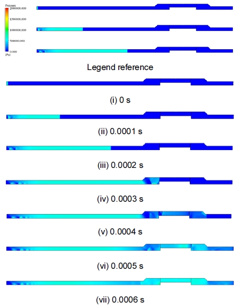
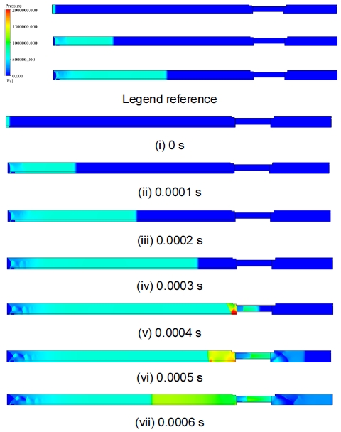
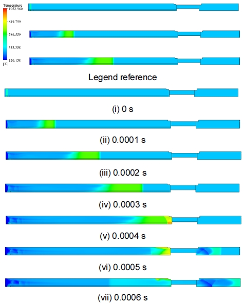
앞서 제시된 모델을 적용하여 화염전파 해석을 실시하였다. 화염 점화를 위해 플라즈마 2.5e7 W/m3의 열원을 유동장 내부에 생성하여 에너지를 공급함으로 점화가 이루어지게 하였다. 해석모델은 총 2가지이며, 각각의 모델에서 내부 역화방지장치가 장착/미장착으로 4가지 해석케이스에 대해 해석을 실시하였다. 각각의 모델에서 역화방지장치 유무에 따른 차이는 3 inch 모델의 경우 Figs. 6-9와 같이 시간 경과에 따라 화염이 출구 쪽으로 전파되는 것을 확인할 수 있으며 그림과 같이 해석 경과 후 약 0.0003초 후에 역화방지장치 영역에 도달하는 것을 확인할 수 있다. 또한 역화방지장치가 장착된 경우는 porous media를 통과하면서 열전달에 의해 수소의 자발화 온도인 약 500℃ 이하로 급감하는 것을 확인할 수 있으며 역화방지장치가 미장착된 경우는 화염온도가 그대로 통과하여 출구까지 전파되는 것을 확인할 수 있다. 이러한 경향은 압력강하의 결과에서도 확인할 수 있으며 2 inch 모델에서 역화방지장치가 장착된 경우 열교환을 촉진하여 화염전파를 방지하는 것을 확인할 수 있다.
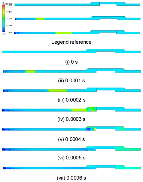
The results of numerical analysis for temperature distribution in case of 2 inch (with flame arrestor)
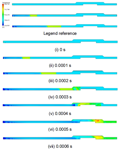
The results of numerical analysis for temperature distribution in case of 2 inch (without flame arrestor)
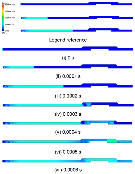
The results of numerical analysis for pressure distribution in case of 2 inch (without flame arrestor)
Figs. 10-13의 3 inch 경우 2 inch의 경우와 동일하게 역화방지장치를 통과하면서 온도가 급감하는 것을 확인할 수 있으며 역화방지장치가 미장착된 경우는 그대로 화염이 통과하여 출구까지 전파된다. 또한 Fig. 14는 X축 좌표에 따라 내부 유도장에서 온도 데이터를 나타내며, 그래프와 같이 역화방지장치가 장착된 경우 자발화 온도 이하로 온도가 급감하는 것을 확인할 수 있다. 그래프에서 X축의 좌표 0을 중심으로 역화방지기가 장착되었으며 2 inch의 경우 그래프와 같이 역화방지기가 장착된 경우는 초기 입구에서 발생한 화염이 출구쪽으로 전파되며 역화방지기를 통과하면서 온도가 극감하는 것을 확인할 수 있다. 하지만 역화방지기가 미장착된 경우는 그래프와 같이 출구쪽으로 화염이 에너지 손실 없이 전파되는 것을 확인할 수 있다.
The results of numerical analysis for temperature distribution in case of 3 inch (with flame arrestor)
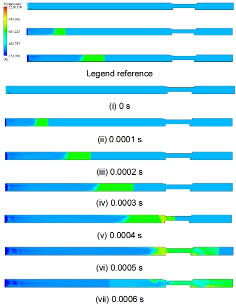
The results of numerical analysis for temperature distribution in case of 3 inch (without flame arrestor)
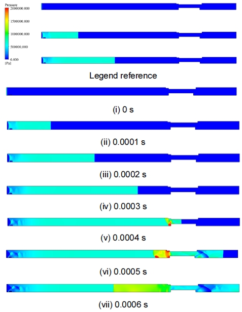
The results of numerical analysis for pressure distribution in case of 3 inch (without flame arrestor)
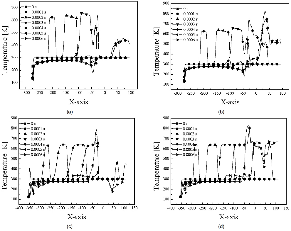
Temperature data according to X-axis. (a) 2 inch (with flame arrestor). (b) 2 inch (without flame arrestor). (c) 3 inch (with flame arrestor). (d) 3 inch (without flame arrestor).
2 inch, 3 inch의 모델에서 역화방지장치가 적용/미적용된 모델에 대해 유동해석을 실시하였으며 결과와 같이 역화방지장치가 장착된 경우 element를 지나면서 역화방지기가 열을 흡수, 발산시켜 반대쪽(protected side)에 있는 가연성 기체가 자연 발화 온도에 오르지 않도록 연소 온도를 감소시키는 것을 확인 유동해석을 통해 확인하였다. 따라서 본 연구에 적용된 모델에 대해 역화방지기 장치를 설치하였을 경우 화염 전파를 억제할 수 있을 것이라 판단된다.
4. 결 론
본 논문은 수소 안전밸브용 화염전파방지장치에 대한 수치해석적 연구로 화염방지장치를 다공성 매질로 가정하여 porous zone의 계수를 구하여 화염방지장치 유무에 대해 수치해석적 연구를 진행하였으며 그 결과는 다음과 같다.
1) 역화방지기 2, 3 inch에 대해 에너지원을 통해 화염생성을 진행하였으며 화염역화방지기를 다공성매질로 가정함에 따라 이를 통과하며 압력 강하 및 열전달에 의한 온도 감소를 확인하였다.
2) 화염방지장치 유무에 따라 화염장치가 장착되었을 경우, 입구부에서 전파된 화염은 화염방지기를 지나 수소의 자발화 온도 500℃ 이하로 온도가 급속히 감소하며 이에 따라 역화방지가 가능할 것이라 판단된다.
3) 화염방지장치에 대한 다공성 매질 가정 및 적용을 통한 역화 수치모사가 가능하며, 동일 연구에 대한 기초자료로 활용 가능할 것이라 판단된다.
Acknowledgments
이 논문은 동아대학교 교내연구비 지원에 의하여 연구되었다.
References
-
J. K. Yeom and J. H. Yoon, “Study of behavior characteristics of emulsified fuels with evaporative field”, Trans. Korean Soc. Mech. Eng. B, Vol. 39, No. 3, 2015, pp. 237-243.
[https://doi.org/10.3795/KSME-B.2015.39.3.237]

-
J. K. Yeom and J. H. Yoon, “Basic study of spray-behavior characteristics of emulsified fuel”, Trans. Korean Soc. Mech. Eng. B, Vol. 38, No. 9, 2014, pp. 763-771.
[https://doi.org/10.3795/KSME-B.2014.38.9.763]

-
M. Huo, S. Lin, H. Liu, and C. F. Lee, “Study on the spray and combustion characteristics of water–emulsified diesel”, Fuel, Vol. 123, 2014, pp. 218-229.
[https://doi.org/10.1016/j.fuel.2013.12.035]

-
S. Y. No, “Application of bio-oils from lignocellulosic biomass to transportation, heat and power generation—a review”, Renew Sustain Energy Rev., Vol. 40, 2014, pp. 1108-1125.
[https://doi.org/10.1016/j.rser.2014.07.127]

-
J. K. Yeom, S. H. Jung, and J. H. Yoon, “An experimental study on the application of oxygenated fuel to diesel engines”, Fuel, Vol. 248, 2019, pp. 262-277.
[https://doi.org/10.1016/j.fuel.2018.12.131]

-
H. W. Lee, D. H. Oh, and Y. J. Seo, “Prediction of changes in filling time and temperature of hydrogen tank according to SOC of hydrogen”, Trans Korean Hydrogen New Energy Soc, Vol. 31, No. 4, 2020, pp. 345-350.
[https://doi.org/10.7316/KHNES.2020.31.4.345]

-
B. H. Park, “Simulation of temperature behavior in hydrogen tank during refueling using cubic equations of state”, Trans Korean Hydrogen New Energy Soc, Vol. 30, No. 5, 2019, pp. 385-394.
[https://doi.org/10.7316/KHNES.2019.30.5.385]

- Ministry of Economy and Finance, “2050 carbon neutral strategy of the republic of Korea”, Ministry of Economy and Finance, 2020. Retrieved from https://www.korea.kr/archive/expDocView.do?docId=39241, .
-
M. A. Bagherian and K. Mehranzamir, “A comprehensive review on renewable energy integration for combined heat and power production”, Energy Conversion and Management, Vol. 224, 2020, pp. 113454.
[https://doi.org/10.1016/j.enconman.2020.113454]

-
M. Mahmoud, M. Ramadan, A. G. Olabi, K. Pullen, and S. Naher, “A review of mechanical energy storage systems combined with wind and solar applications”, Energy Conversion and Management, Vol. 210, 2020, pp. 112670.
[https://doi.org/10.1016/j.enconman.2020.112670]

-
M. Li, Y. Bai, C. Zhang, Y. Song, S. Jiang, D. Grouset, and M. Zhang, “Review on the research of hydrogen storage system fast refueling in fuel cell vehicle”, Int. J. Hydrog. Energy, Vol. 44, No. 21, 2019, pp. 10677-10693.
[https://doi.org/10.1016/j.ijhydene.2019.02.208]

-
J. Zheng, J. Guo, J. Yang, Y. Zhao, L. Zhao, X. Pan, J. Ma, and L. Zhang, “Experimental and numerical study on temperature rise within a 70 MPa type III cylinder during fast refueling”, Int. J. Hydrog. Energy, Vol. 38, No. 25, 2013, pp. 10956-10962.
[https://doi.org/10.1016/j.ijhydene.2013.02.053]

-
J. Guo, J. Yang, Y. Zhao, X. Pan, L. Zhang, L. Zhao, and J. Zheng, “Investigations on temperature variation within a type III cylinder during the hydrogen gas cycling test”, Int. J. Hydrog. Energy, Vol. 39, No. 25, 2014, pp. 13926-13934.
[https://doi.org/10.1016/j.ijhydene.2014.03.097]

-
N. de Muguel, R. O. Cebolla, B. Acosta, P. Moretto, F. Harskamp, and C. Bonato, “Compressed hydrogen tanks for on-board application: thermal behaviour during cycling”, Int. J. Hydrog. Energy, Vol. 40, No. 19, 2015, pp. 6449-6458.
[https://doi.org/10.1016/j.ijhydene.2015.03.035]

-
C. P. Fowler, A. C. Orifici, and C. H. Wang, “A review of toroidal composite pressure vessel optimisation and damage tolerant design for high pressure gaseous fuel storage”, Int. J. Hydrog. Energy, Vol. 41, No. 47, 2016, pp. 220647-22089.
[https://doi.org/10.1016/j.ijhydene.2016.10.039]

-
J. Zheng, X. Liu, P. Xu, P. Liu, Y. Zhao, and J. Yang, “Development of high pressure gaseous hydrogen storage technologies”, Int. J. Hydrog. Energy, Vol. 37, No. 1, 2012, pp. 1048-1057.
[https://doi.org/10.1016/j.ijhydene.2011.02.125]

-
S. J. Ko, B. W. Kim, J. H. Park, G. H. Kang, and S. K. Lee, “Analysis of quenching performance of in-line flame arrester by analyzing temperature characteristics of body”, Journal of the KNST, Vol. 3, No. 1, 2020, pp. 8-13.
[https://doi.org/10.31818/JKNST.2020.03.3.1.8]

-
Y. Okawa, S. Asano, C. Youn, S. Ikeda, and T. Kagawa, “Experimental research on a newly developed detonation flame arrester”, SICE Annual Conference, 2008, pp. 1088-1091.
[https://doi.org/10.1109/SICE.2008.4654819]

-
H. I. Joo, K. Duncan, and G. Ciccarelli, “Flame-quenching performance of ceramic foam”, Combustion Science and Technology, Vol. 178, No. 10-11, 2006, pp. 1755-1769.
[https://doi.org/10.1080/00102200600788692]

-
M. H. Mat Kiah and R. M. Kasmani, “Experimental study on premixed flame acceleration in closed pipe”, Jurnal Teknologi, Vol. 62, No. 1, 2013, pp. 45-51.
[https://doi.org/10.11113/jt.v62.1322]

- S. Z. sulaiman, R. M. Kasmani, and A. Mustafa, “Experimental study on the effect of curved tube of premixed hydrogen-air explosion”, Journal of Engineering Science and Technology, Special Issue on SOMCHE 2014 & RSCE 2014 Conference, pp. 50-60, 2015.
- ANSYS, “ANSYS FLUENT theory guide”, ANSYS, 2020. Retrieved from http://www.pmt.usp.br/academic/martoran/notasmodelosgrad/ANSYS%20Fluent%20Theory%20Guide%2015.pdf, .
-
R. Nowak, “Estimation of viscous and inertial resistance coefficients for various heat sink configurations”, Procedia Engineering, Vol. 157, 2016, pp. 122-130.
[https://doi.org/10.1016/j.proeng.2016.08.347]

- J. I. Lim, J. H. Park, J. H. Kim, and D. J. Kim, “Flow analysis of sea-water strainer”, Korean Society for Fluid Machinery, 2009, pp. 333-334. Retrieved from https://www.dbpia.co.kr/Journal/articleDetail?nodeId=NODE01356715, .

