한국수소및신에너지학회 학술지영문홈페이지
[ Article ]
Transactions of the Korean Hydrogen and New Energy Society - Vol. 31, No. 1, pp.65-72
ISSN: 1738-7264 (Print) 2288-7407 (Online)
Print publication date 28 Feb 2020
Received 21 Nov 2019 Revised 03 Feb 2020 Accepted 28 Feb 2020
DOI: https://doi.org/10.7316/KHNES.2020.31.1.65

패키지형 수소충전소의 고장형태별 영향 분석

서두현1 ; 이광원2, ; 김태훈2
1피에스피
2호서대학교
A Study on the Hazard Factor of Packaged Hydrogen Station by Failure Mode & Effects Analysis
DOO HYOUN SEO1 ; KWANG WON RHIE2, ; TAE HUN KIM2
1Process Safety Partner (PSP), 261 Solchi-ro, Asan 31498, Korea
2Hoseo University, 20 Hoseo-ro 79beon-gil, Baebang-eup, Asan 31499, Korea

Correspondence to: kwrhie@hoseo.edu

2020 The Korean Hydrogen and New Energy Society. All rights reserved.

Abstract

In this study, the purpose is to identify the risks of the facilities of packaged hydrogen stations. As a risk identification method, failure mode & effect analysis (FMEA), a qualitative risk assessment, was used to analyze failure mode and effects of component of each facility. The analysis criteria were used to derive the risk priority number (RPN) using the 5-point method according to severity, incidence, and detectability. The study analyzed a total of 141 components of 23 types that can be identified on the design of the packaged hydrogen filling station. As a result, 683 types of failures and their causes and effects were identified. and the RPN was number of a total of 1,485. Of these, 10 failure types with a RPN value of 40 or more were deemed necessary. In addition, a list of failure types with a severity score of 5 was identified and analyzed.

Keywords:

Pakeged hydrogen station, Hazard factor, FMEA, Qualitative assessment, Risk assessment

키워드:

패키지형 수소충전소, 유해요인, 고장형태영향분석, 정성적 평가, 위험성평가

1. 서 론

미국, 일본, 유럽 등 해외의 여러 나라에서 수소의 대중화를 위하여 여러 정책과 인프라를 구축하고 있다. 미국에서는 2023년까지 수소충전소 100기 구축하기 위하여 매년 2,000만$를 지원하고 있다1). 일본은 2025년까지 수소충전소 160기를 구축할 예정이다2). 유럽은 2030년까지 재생 가능 에너지를 27%로 늘리는 것을 목표로 하고 있다3). 이러한 목표는 충전소의 부지 확보 및 관련 법령의 안전기준을 충족해야 하기에 물리적 한계를 해결하고자 해외에서도 패키지형 수소충전소의 개발 및 실용화를 진행 중이다. 현재 덴마크의 기업 중 한 곳은 컨테이너 형태의 패키지형 충전소의 설계, 제조 능력을 확보하고 있고4), 일본의 경우 독자적으로 개발한 전기 시스템을 적용한 패키지형 수소충전소를 운영하고 있다5).

국내에서도 수소의 안전성과 효율, 대중화를 위해 정책사업과 수소 전지차량, 충전소 등 여러 인프라 구축에 힘쓰고 있다6,7). 장기적인 계획으로 국내 상황에 맞게 기존의 CNG, LPG의 설비에 수소충전소 결합한 융·복합 충전소의 건축이 진행 중에 있다. 또한, 하나의 컨테이너에 수소의 압축·충전을 할 수 있도록 하는 패키지형 수소충전소를 개발하여 부지 확보 및 안전거리 확보 등의 인프라 구축 방안을 활용 중에 있다8,9).

패키지형 수소충전소는 하나의 컨테이너에 수소를 압축 및 충전하는 설비이므로 기존의 부품과는 다른 새로운 설계와 구조가 요구된다. 이에 본 연구는 패키지형 수소충전소의 구조와 설계에 따른 부품별 세부 위험요소를 도출하고자 고장형태 및 영향분석(failure mode and effect analysis, FMEA)을 이용하여 잠재위험요소의 심각도, 발생도, 검출도 등을 고려한 부품별 위험성 정도를 평가하였다.


2. 실 험

2.1 패키지형 수소충전소의 개요

패키지형 충전소는 수소자동차의 충전에 필요한 설비를 모듈화하여 하나의 보호함에 장착한 충전시설로 일반적 수소충전소에서 지켜야 할 안전거리(이격거리)를 확보하는 데 있어 유리하며, 이동설치가 용이한 설비를 말한다9).

패키지형 수소충전소의 대략적인 구성은 Fig. 1과 같으며 공정흐름을 살펴보면 우선 튜브 트레일러(tube trailer)에서 수소를 공급받아 이송 패널(decant panel)로 조정하며 안정적으로 압축기(compressor)로 공급한다. 압축기(compressor)에서는 공급받은 180 bar의 수소를 400 bar 또는 800 bar로 승압하며, 승압된 수소는 자동선별패널(priority fill panel)에서 저장탱크(storage)로 저장 또는 차량 충전기(dispenser)로 선택적으로 공급하여 차량에 충전하게 된다. 이때 저장탱크(storage)에서는 400 bar와 800 bar로 나뉘어 저장된다. 자동차에 충전할 때는 400 bar에서 800 bar로 순차적으로 충전하게 된다.

Fig. 1.

Block diagram of packaged hydrogen station

2.2 공정흐름 및 부품

패키지형 수소충전소의 공정흐름도(process flow diagram, PFD)는 Fig. 2와 같다.

Fig. 2.

PFD of packaged hydrogen station

Fig. 2에서와 같이 검은색 테두리 영역 내부가 패키지형 수소충전소 모듈의 부분이며, 튜브 트레일러(tube trailer) 및 수소저장탱크(H2 storage), 충전기(dispenser) 등에 연결하여 사용이 가능한 형태이다.

패키지형 수소충전소의 주요 부품은 다음과 같이 각 장치별로 구분할 수 있다. 공급패널(decant panel)은 check valve (CV), needle valve (NV), pressure safety valve (PSV), pressure alarm low (PAL), pressure indicator (PI), pressure transmitter (PT), filter (F)로 구성되어 있다. 기능으로는 튜브 트레일러로부터 180 bar의 수소를 받고 질소를 보내주는 역할을 한다.

압축기(compressor)는 auto operation valve (AOV), ball valve (BV), temperature transmitter (TT), PSV, NV, CV, F, PAL, PI, PT로 구성되어 있으며, 기능은 180 bar의 수소를 400 bar 또는 800 bar로 압축하는 역할을 한다.

자동선별패널(priority fill panel)은 flow control valve (FCV), flow indicator controller (FIC), flow indicator (FI), flow indicator transmitter (FIT), pressure alarm high (PAH), AOV, CV, NV, PI, PT로 구성되어 있으며, 기능은 압축된 수소를 저장용기로 보내거나 충전기(dispenser)로 보내주거나 압축기(compressor)로 보내는 역할을 한다.

수소저장탱크(H2 storage)는 NV, PSV, cylinder로 구성되어 있으며, 기능은 400 bar 또는 800 bar로 압축된 수소를 저장한다.

충전기(dispenser)는 CV, PSV, NV, BV, FCV, F, PT, PI로 구성되어 있으며, 기능은 수소를 충전차량으로 보내주는 역할을 한다.

수소 예비 냉각기(H2 pre cooler)는 temperature alarm high (TAH), temperature indicator (TI), TT, NV, PSV로 구성되어 있으며, 기능은 충전기(dispenser)에서 온 수소의 온도를 낮춰주고 다시 충전기(dispenser)로 보내는 역할을 한다.

N2 gas system을 pressure relief valve (PRV), nitrogen bottle, BV, NV, PSV로 구성되어 있으며, 기능은 저장되어 있는 질소를 사용하여 AOV를 조작하는 역할을 한다.

2.3 위험요소 도출 기법 및 기준

본 연구에서 패키지형 수소충전소의 위험요소를 도출하기 위한 방법으로 제품 및 설비의 고장형태별 영향을 분석에 적합한 failure mode & effect analysis (FMEA)를 활용하였다. 특히 FMEA는 시스템이나 서브시스템의 위험분석을 진행하기 위해 사용되는 전형적인 상향식 귀납적 분석방법이며 정성적 안전성 평가의 대표라고 할 수 있다. 또한 결함과 상위 수준의 기능적 제품에 미치는 영향과 메커니즘을 연구하는 데 적합하여 현재에도 제품의 품질 및 수명연구에 활용되는 방법이다10).

또한 FMEA의 경우, 세부부품별로 위험요소 및 고장의 형태 등을 도출하는 것뿐만 아니라 critical analysis (CA) 등을 적용함으로써 고장 영향의 피해정도를 예측하여 정량화적 분석이 가능하다. 일반적으로 치명도(critical) 분석까지 포함된 FMECA에서는 각 고장형태에 따른 위험요소별로 심각도, 발생도, 검출도를 평가함으로써 중요 위험요소 및 중요부품 등을 나열할 수 있으며, 이를 통해 부품의 점검 및 교체시기를 결정하거나 주요 관리 포인트 등을 예측하는 데 활용할 수 있다.

심각도, 발생도, 검출도를 통해 계산되는 위험성의 정도는 위험우선순위(risk priority number, RPN)는 다음의 수식으로 산출된다.

RPN=Severity×Ocurrence×Detectability

일반적으로 심각도, 발생도, 검출도는 10점법 또는 5점법을 사용하며, 각 점수를 모두 곱하여 위험우선순위를 결정함으로써 상대적인 위험요소의 순위를 결정하게 된다. 본 연구에서는 5점법을 활용하였으며, 평가의 기준은 다음과 같이 결정하였다.

Table 1의 경우 심각도(severity)로서 심각한 정도에 따라 5단계로 구분하였으며, Table 2의 발생도(occurrence)는 수소충전소 운영 수명을 기준으로 사고발생의 빈도를 구분하였다. 또한, Table 3의 검출도(detectability)의 경우 현 관리에서 고장의 형태 및 위험요소의 명확한 확인의 정도로 구분하여 세 가지 평가기준 모두 1점은 가장 위험성의 정도가 낮은 상태, 5점은 가장 위험성이 높은 상태로 평가하였다.

Criteria of assessment by severity

Criteria of assessment by occurrence

Criteria of assessment by detachability

2.4 세부부품별 위험요소 도출

본 연구의 대상으로 선정한 패키지형 수소충전소는 튜크 트레일러(tube trailer)를 연결하여 수소를 공급하는 설비로 핵심이 되는 압축기 및 선별 패널(priority panel)의 주요 부품에 대해 실시하였으며 설계 P&ID 및 사양서 등을 통해 모든 부품의 세밀한 분석을 진행하였다. 단, P&ID 및 상세 사양의 경우 기업의 비밀이 포함되어 공개되지 않으며, 설비의 설계자 및 충전소 전문가 등을 포함한 평가팀을 구성하여 진행하였다.

평가의 대상인 부품은 총 23종으로 구분되며 141개의 부품에 대해 진행하였고 같은 기능을 하는 부품은 하나의 그룹으로 분류하여 진행하였다. 평가에 포함된 부품의 list는 Table 4와 같다.

List of component with function

평가 대상 부품은 형태(type)별로 구분하였으며, 동일한 형태의 부분이라 할지라도 사용 용도에 따라 사용 유체, 사용 압력, 사용 빈도 등의 다양한 변수가 작용할 수 있기에 각기 평가를 달리하였다.

패키지형 수소충전소의 FMEA sheet의 예시는 Table 5와 같다.

Sample sheet of FMEA about PSV

2.5 평가 결과

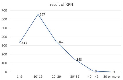
각 부품에 대한 고장형태, 원인 및 영향에 대해 예측을 하였으며, 각각의 고장형태별 시나리오별로 그로 인한 피해의 심각도나 발생도, 검출도를 앞선 기준을 통해 위험우선순위(RPN)를 산정하였다. 결과를 요약하면 Table 6과 같으며, Fig. 3과 같은 분포를 보인다.

Summary of FMEA results (RPN by failure mode)

Fig. 3.

Number of RPN

FMEA 결과를 종합하여 보았을 때, 가장 높은 점수가 60점이 나왔으며, 가장 많은 점수는 12점으로 286개가 나왔다.

총 1,485개의 RPN 개수 중 우선적으로 조치해야한다고 판단되는 점수를 40점 이상으로 정하였고, 40점 이상 되는 개수는 10개로 나왔다.

이를 바탕으로 패키지형 수소충전소의 설계도면상에서 예측되는 위험 중 우선적으로 조치를 해야하는 것이 10개이며, 이는 기준에 따라 늘어나거나 줄어들 수 있다. 그중에서 RPN이 40 이상인 부품과 그 고장형태에 대해서 살펴보면 Table 7과 같다.

List of components of high risk priority number

고위험에 해당되는 주요 부품 중 개선이 시급한 부분으로 PSV를 확인할 수 있다. 주로 보이는 고장형태로는 막힘과 열림 실패가 있고 이를 개선하기 위해 밸브를 보수하거나 배관 분리 시 이물질이 유입되지 않도록 주의해야 할 것으로 예상된다.

또한, 수소 외부누출의 고장형태를 예측하였고, 이를 개선하기 위한 조치사항으로 밸브와 배관의 체결확인이 필요하고 실링(sealing)이 정상적으로 되었는지도 확인해야 한다.

위 평가 결과 이외에도 심각도가 높은 점수여도 발생도와 검출도 점수가 낮은 경우 RPN값이 낮게 산출되는 경우가 많이 있다. 그러나 RPN이 작게 산출되었다 하더라도 단 한 번의 사고가 심각한 영향을 줄 수 있는 경우를 고려할 필요가 있다. 즉 심각도가 5점인 고장형태를 따로 파악하고 분석할 필요가 있다. 심각도가 5점으로 매우 심각한 경우의 고장형태는 Table 8과 같다.

List of failure mode with 5 point severity (high risk)

이처럼 심각도가 5점으로 도출된 부품 및 고장형태는 패키지형 수소충전소의 설계도면상 안전성을 확보하기 위해서는 해당 부품과 그 고장형태의 개선사항도 필요하다. 13개의 부품 중 38가지의 고위험에 해당될 수 있는 고장형태를 발견하였으며, 주요 고장영향으로는 수소누출 및 폭발, 배관 및 밸브 파열이 있다. 이를 위한 주요 권고조치 사항으로는 밸브 초기 설치 시 완벽하게 체결해야 하며, 밸브의 열림/닫힘 표시, 바이패스 설치가 있다.


4. 결 론

본 연구에서는 패키지형 충전소에 대한 설비의 위험성을 파악하고자 정성적 위험성 평가 기법인 FMEA를 활용하여 각각의 설비의 부품별 고장형태와 영향을 분석하였다.

평가기준에 따른 심각도, 발생도, 검출도를 5점법을 사용하여 RPN을 도출한 후 패키지형 충전소의 설계도면상에서 파악할 수 있는 총 23종 141개 부품을 평가하였고, 683개 고장형태와 이들의 원인 및 영향을 분석하여 각각의 1,485개의 RPN값을 도출하였다. 이 중 보완조치가 필요하다고 사료되는 RPN값 40점 이상인 10개의 고장형태를 도출하였고, 그 외에 심각도 5점인 고장형태의 목록 파악 및 분석을 하였다.

평가를 통해 도출된 주요 고장형태로는 외부/내부 누출로 인한 수소 누출 및 폭발, 구조적 결함을 인한 수소누출 및 밸브 파손, 열림/닫힘 실패로 인한 긴급 상황 발생 및 폭발, 막힘으로 밸브 및 배관 파열 등이 있다. 이를 위한 주요 권고조치사항으로 수소누출 및 폭발로 인한 경고문구 표시 또는 보호가드 설치 확인과 밸브 및 배관 파열로 인한 설치 전 제품, 밸브 검사를 철저히 해야 한다. 긴급 상황 시 대처가 가능한 작업자에 대한 공정 매뉴얼과 정기교육이 필요함을 볼 수 있다.

위험성 평가를 통해 우선적으로 개선해야 할 사항을 보여줌으로써 설계상의 부족한 부분을 채울 수 있다. 그리고 FMEA에서 확인이 어려운 위험요소에 대해 HAZOP 및 기타 위험성 평가가 추가로 진행되어야 할 것이고, 향후 정량적 위험성 평가 및 피해예측을 통해 사회적 위험도에 대한 고찰이 확보되어야 할 것으로 사료된다.

Acknowledgments

이 논문은 에너지기술평가원 에너지국제공동연구사업(20178520040490)에 의하여 연구되었음에 감사드립니다.

References

  • Hydrogen Progress, Priorities and Opportunities (HyPPO), “A California road map: the commercialization of hydrogen fuel cell vehicles”, California Fuel Cell Partnership (CaFCP), 2014, pp. 3-4. Retrieved from https://www.slideshare.net/Cwhite3655/hydrogen-progress-priorities-and-opportunities, .
  • E. Ohira, “NEDO’s activity on CO2-free hydrogen”, New Energy and Industrial Technology Development Organization (NEDO), 2017, pp. 3. Retrieved from http://injapan.no/wp-content/uploads/2017/02/6-NEDO-Activity-on-CO2-free-H2.pdf, .
  • J. H. Park and U. S. Yang, “World energy issue insight”. Korea Energy Economics Institute, 2016, pp. 20. Retrieved from http://www.keei.re.kr/web_keei/d_results.nsf/0/5A5001828127B46F4925808D00428847/$file/WEIS1603.PDF, .
  • S. H. Jang, “Significantly reduce the cost of building hydrogen stations”, Today Energy, 2016. Retrieved from http://www.todayenergy.kr/news/articleView.html?idxno=118261, .
  • H. Yoichilo, “Tatami station that produces hydrogen from water”, Smart Japan, 2014. Retrieved from https://www.itmedia.co.jp/smartjapan/articles/1409/22/news038.html, .
  • Future Strategy Team, “Proposals and trends of hydrogen fuel cell vehicle (FCEV)”, Korea Petroleum Association, 2018. Retrieved from URL http://www.google.co.kr/url?sa=t&rct=j&q=&esrc=s&source=web&cd=2&ved=2ahUKEwjNj52cpLznAhXUMd4KHXTSBFEQFjABegQIAxAB&url=http%3A%2F%2Fwww.petroleum.or.kr%2Fm%2Fprogram%2Fpolicy%2Fdownload.php%3Fid%3D542&usg=AOvVaw07q6iemp8Wx7g_AmQz5OiT, .
  • K. J. Cho, “Packaged hydrogen station, not far from localization”, H2 News, 2017. Retrieved from http://www.h2news.kr/news/article.html?no=6060, .
  • Ministry of Environment, “Subsidy guidelines for the supply of hydrogen fuel cell vehicles and charging station installation business”, Ministry of Environment, 2019. Retrieved from URL http://www.me.go.kr/home/web/policy_data/read.do?menuId=10262&seq=7297, .
  • Ministry of Trade, Industry and Energy, “Exception standards for facility standards of combined and packaged car filling stations”, 2018. Retrieved from http://www.law.go.kr/행정규칙/융·복합,패키지형및이동식자동차충전소시설기준등에관한특례기준/(2018-179,20181001), .
  • D. S. Oh, “A study of the status and safety assessment of domestic and foreign hydrogen station”, A Master´s thesis of Hoseo University, 2009. Retrieved from http://www.riss.kr/search/detail/DetailView.do?p_mat_type=be54d9b8bc7cdb09&control_no=4fb73bf7337da589ffe0bdc3ef48d419, .

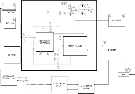
Fig. 1.

Fig. 1.
Block diagram of packaged hydrogen station

Fig. 2.

Fig. 2.
PFD of packaged hydrogen station

Fig. 3.

Fig. 3.
Number of RPN

Table 1.

Criteria of assessment by severity

Severity (S) Contents
5 Catastrophic accident (people's damage + property damage), be unable to do operation
4 Critical accident (property damage)
3 Bad production, marginal accident (suspension of operation)
2 Minor accident, pause operation
1 Negligible accident, (no damage)

Table 2.

Criteria of assessment by occurrence

Occurrence (O) Contents
5 Occurs about once in 1 year
4 Occurs about once in 5 year
3 Occurs about once in 10 year
2 Occurs about once in 100 year
1 Almost no frequency of occurrence (1/1,000 years)

Table 3.

Criteria of assessment by detachability

Detectability (D) Contents
5 Probability of detection impossible
4 Probability of detection is slim but possible
3 Low probability of detection
2 Confirmation through management system
1 High probability of detection by prefecture management, also visible with the naked eye

Table 4.

List of component with function

No Component Function
Needle valve NV 1101, 1102 Located on piping connected to priority panel boosted to 800 bar from compressor
NV 1103 Repair valve for PI, PT of N2 header
NV 1104, 1704 Drain valve in N2 line (always closed)
NV 1001, 1002, 1101A, 1102A Valve in piping line to transfer hydrogen
NV 1003 Repair valve in N2 line
NV 1004, 1007, 1108A, 1301 Vent valve for residual hydrogen gas
NV 1005, 1006, 1104A, 1105A, 1106A, 1107A, 1304, 1305, 1700, 1702, 1703 Repair valve for PI, PT of hydrogen line
NV 1108, 1103A Repair valve for filter
NV 1300, 1302, 1303, 1306 Valve in hydrogen line to pre cooler
NV 1107 Valve of line for recovering hydrogen from the dispenser
NV 1400, 1401, 1402, 1403, 1404, 1405, 1406, 1407 Repair valve in hydrogen storage tank
NV 1500, 1501, 1502 Repair valve in hydrogen pre cooler
NV 1600 Repair valve for PI of cooling water
Ball valve BV 1001, 1101, 1300, 1700, 1701 Repair valve in N2 line
BV 1600, 1601 Repair of cooling water tank and water cooler line
BV 1103 Valve for cooling water supply of cooling water tank
BV 1604, 1113A Drain valve for cooling water tank
Auto valve AOV 1101, 1101A Open during compression from 180 bar to 400 bar
AOV 1102, 1101A, 1203 Open during compression from 400 bar to 800 bar
AOV 1201, 1204 Open when stored in a 400 bar storage tank
AOV 1201 Open when stored in a 800 bar storage tank
AOV 1205, 1301 Open when charging with dispenser in 400 bar storage tank
AOV 1202, 1301 Open when charging with dispenser in 800 bar storage tank
AOV 1206, 1301 Open when charging from compressor to disperser
AOV 1207 Open when recovering residual gas
AOV 1302 Vent lines with residual gas recovery
Flow control valve FCV 1101 Boosting line hydrogen flow control from 400 bar to 800 bar
FCV 1200 Flow control when filling the car
Check valve CV 1001, 1101, 1102, 1101A, 1300, 1303 Prevent hydrogen backflow at the hydrogen line
CV 1002 Prevent hydrogen backflow at the nitrogen line
CV 1003, 1004, 1005, 1301, 1302 Prevent air backflow at the vent line
CV 1600 Prevent backflow between the water cooler and the cooling supply motor
CV 1700 Prevent nitrogen backflow at the nitrogen gas system
Regulator PRV 1700 Pressure control of nitrogen gas system
Pressure safety valve PSV 1001, 1101A, 1102A, 1300, 1400, 1401, 1402, 1403 Device for the emergency release of hydrogen from vent line
PSV 1103A, 1500 Device for pressure release during cooling water thermal expansion in a cooling device
PSV 1700, 1701 Device for nitrogen release from N2 gas system
Pressure indicator PI 1001A, 1101A, 1102A, 1203, 1302 Hydrogen pressure indication in the hydrogen line
PI 1201 Pressure indication at 800 bar storage line
PI 1202 Pressure indication at 400 bar storage line
PI 1200, 1701, 1702 Nitrogen pressure indication in the nitrogen line
PI 1703 Nitrogen pressure indication in N2 gas system vent line
PI 1601 Pressure indication on the water cooler coolant supply line
Pressure transmitter PT 1001, 1101A, 1102A, 1201, 1202, 1203, 1302 Transfer of nitrogen pressure measured in hydrogen line
PT 1101 Transfer of hydrogen pressure measured in nitrogen supply line
Pressure alarm PAL 1001, 1101, 1101A, 1103A
PAH 1102A, 1201, 1202, 1203
Alarm operation with measured pressure signal low & high
Temperature indicator TI 1101A Indicate of hydrogen temperature in the compressor
TI 1501 Indicate of hydrogen temperature cooled by the pre cooler
Temperature transmitter TT 1101A, 1501 Transfer of hydrogen temperature from compressor
TT 1502, 1601 Transfer of coolant temperature from coolant line
Temperature alarm TAH 1101A, 1501 Alarm operation with measured temperature signal
Flow indicator FI 1300 Flow indication of the line from the priority panel to the dispenser
Flow transmitter FIT 1300 Flow transfer of lines from priority panel to dispenser
Flow control FIC 1300 Flow control of the line from the priority panel to the dispenser
Flow record FR 1101 Nitrogen flow recorder of nitrogen gas system
Compressor Compressor A, B, C Compression from 180 bar hydrogen to 400 bar or compression from 400 bar hydrogen to 800 bar
Control panel Priority panel Automatic control of hydrogen line during hydrogen compression, storage and charging
Storage tank Cylinder @1400, 1401, 1402, 1403 Hydrogen storage compressed to 400 bar or 800 bar
Filter F 1101, 1101A, 1102A, 1301 Filter for removing foreign substances from hydrogen line
Cooler H2 Pre Cooler Hydrogen cooling on charge in dispenser
Chiller H2 Chiller Cool the coolant in the H2 pre cooler

Table 5.

Sample sheet of FMEA about PSV

Component PSV 1001. 1101A, 1102A, 1300, 1400, 1401, 1402 FMEA
────
Page 47 of 90
FMEA 2018 . 11 . 17
Function Failure mode Effects S Cause/Mechanism O Management D RPN Action
Device for
the
emergency
release of
hydrogen
from vent
line
External leakage Hydrogen explosion 5 • Incorrect PSV installation by operator
• Sealing defect
4 • Installation of gas detecter 1101 1 20 • Training to installation worker
• Indication of use location by parts
5 • PSV pressure design error 2 • Installation of gas detecter 1101 1 10 • PSV inspection before installation
Internal leakage Hydrogen leak 4 • Structural failure of the valve 3 • Installation of gas detecter 1101 2 24 • PSV inspection before installation
Efficiency decline of process 3 • Dust accumulation to valve 3 • Installation of filter 1101 3 27 • Install additional filters
3 • Deterioration of the valve
• Structural failure of the valve
3 • Check to leak of regular
• Installation of gas detecter 1101
1 9 • Use of certified products
• Perform regular inspection
• PSV inspection before installation
Fail to close Efficiency decline of process 3 • Deterioration of the valve
• Structural failure of the PSV
3 • Installation of gas detecter 1101 1 9 • Use of certified products
• Perform regular inspection
Hydrogen explosion 5 • Deterioration of the valve
• Structural failure of the PSV
3 • Installation of gas detecter 1101 1 15 • Use of certified products
• Perform regular inspection
Fail to open Rupture of the pipe or valve 5 • Structural failure of the PSV 2 • Installation of gas detecter 1101 3 30 • Training to installation worker
Process stop 4 • Incorrect PSV installation by operator 4 • Installation of gas detecter 1101 1 16 • Perform regular inspection
4 • Deterioration of the valve 3 • Installation of gas detecter 1101 2 24 • Perform regular inspection
Fail to vent 4 • Structural failure of the PSV 2 • Installation of gas detecter 1101 2 16 • PSV inspection before installation
5 • Incorrect PSV installation by operator 4 • Installation of gas detecter 1101 1 20 • Training to installation worker
Blockage Rupture of the pipe or valve 5 • Incorrect PSV installation by operator 4 • Check a test run of process 3 60 • Training to installation worker
Process stop 3 • Deterioration of the valve 3 • Check a test run of process 3 27 • Perform regular inspection
Fail to vent 4 • Dust accumulation to valve 3 • Check a test run of process 3 36 • Install additional filters
4 • Incorrect PSV installation by operator 4 • Check a test run of process 3 48 • Training to installation worker
4 • Deterioration of the valve 4 • Check a test run of process 3 48 • Perform regular inspection
   

Table 6.

Summary of FMEA results (RPN by failure mode)

RPN Amount
1~9 333
10~19 657
20~29 342
30~39 143
40~ 10
Total 1,485

Table 7.

List of components of high risk priority number

Component Failure mode Effect Cause
PSV Blockage Rupture of the pipe or valve Operator human error to installation
Fail to vent Operator human error to installation
Deterioration of the valve
Fail to open Rupture of the pipe Incorrect PSV installation by operator
Blockage Rupture of the pipe or valve Incorrect PSV installation by operator
Fail to open Rupture of the pipe or valve Operator human error to installation
NV External leakage Hydrogen explosion Faulty to bonding and sealing
Needle valve damage and defect
FCV Blockage Rupture of the pipe Structural defects
Compressor External leakage Hydrogen explosion Faulty to bonding and sealing

Table 8.

List of failure mode with 5 point severity (high risk)

Component Failure mode Component Failure mode
AOV
(auto valve)
External leakage FCV External leakage
Fail to open Blockage
Fail to close Structural defects
Minor problem CV External leakage
Structural defects Fail to open
NV
(needle valve)
External leakage Fail to close
Fail to close Blockage
Blockage PSV External leakage
Structural defects Fail to close
PI Error to indicator Fail to open
Malfunctions Blockage
Not measurable TAH Error to receive
PT Error to transfer Inoperable
Error to receive Structural defects
PAL/PAH Inoperable Compressor External leakage
Error to receive Internal leakage
Priority panel External leakage Fail to stop
Filter Blockage Cylinder External leakage
Structural defects