Raney Ni-Zn-Fe 전극의 산소발생 반응 특성에 미치는 도금변수의 영향
2020 The Korean Hydrogen and New Energy Society. All rights reserved.
Abstract
The intermittent characteristics of renewable energy complicates the process of balancing supply with demand. Electrolysis technology can provide flexibility to grid management by converting electricity to hydrogen. Alkaline electrolysis has been recognized as established technology and utilized in industry for over 100 years. However, high overpotential of oxygen evolution reaction in alkaline water electrolysis reduces the overall efficiency and therefore requires the development of anode catalyst. In this study, Raney Ni-Zn-Fe electrode was prepared by electroplating and the electrode characteristics was studied by varying electroplating parameters like electrodeposition time, current density and substrate. The prepared Raney Ni-Zn-Fe electrode was electrochemically evaluated using linear sweep voltammetry. Physical and chemical analysis were conducted by scanning electron microscope, energy dispersive spectrometer, and X-ray diffraction. The plating time did not changed the morphology and composition of the electrode surface and showed a little effect on overpotential reduction. As the plating current density increased, Fe content on the surface increased and cauliflower-like structure appeared on the electrode surface. In particular, the overpotential of the electrode, which was prepared at the plating current density of 320 mA/cm2, has showed the lowest value of 268 mV at 50 mA/cm2. There was no distinguishable overpotential difference between the type of substrate for the electrodes prepared at 80 mA/cm2.
Keywords:
Alkaline water electrolysis, Oxygen evolution reaction, Electroplating, Ni-Zn-Fe alloy, Anode키워드:
알칼라인 수전해, 산소 발생 반응, 전기도금, 니켈-아연-철 합금, 산화전극1. 서 론
최근 재생에너지의 전력생산 점유율이 지속적으로 증가하고 있지만 재생에너지는 간헐적이며 변동성이 커 전력계통의 안정화를 위해 이를 저장할 필요가 있다1-4). 에너지 저장 방법으로 전기화학적 수소생산 기술이 주목받고 있으며, 수전해로 생산된 수소는 높은 에너지 밀도를 가진 청정에너지 캐리어로써 탄소배출 없이 생산이 가능하다5,6).
알칼라인 수전해는 오랜 기간 동안 연구되어 왔으며 이미 실용화 된 기술이고, 촉매로는 귀금속보다 저렴하며 알칼라인 용액에 강한 내부식성을 가진 Ni을 기반으로 연구되어왔다7-10). 특히 알칼라인 수전해의 산소발생 반응은 4전자 이동 반응으로 높은 과전압으로 인한 낮은 활성을 개선하는 연구가 진행되고 있다10,11). 비교적 낮은 산소발생 반응 활성을 갖는 Ni은 Fe, Ce, Co, Cu, La, Mo 등과 함께 합금을 만들어 이용하면 비교적 활성을 높일 수 있다는 연구가 보고되어 있다12-14). Kim 등15)은 Ni-Cu-P를 합금화하여 이용할 경우 촉매활성에 영향을 주는 표면적을 증가시킬 수 있어 산소발생 반응 과전압 감소에 효과가 있다고 보고하였다. Li 등16), Burke 등17)의 연구에 따르면 Ni-Fe 합금의 경우 활성이 다른 합금에 비해 높으며 Ni 및 Fe 함량 비율에 따른 활성이 달라 최적의 조성비를 맞추어야 한다고 보고하였다. 또한 전극의 비표면적을 넓히기 위해 Ni과 Zn, Al 성분의 합금 제조 후 dealloying을 통한 Raney Ni 전극의 연구가 있어 왔다18,19). Sheela 등20)의 연구에 의하면 Zn가 약 50 wt.% 함유된 Ni-Zn 전극은 dealloying 후 충분한 잔류 Ni 양과 많은 균열로 인하여 높은 표면적을 가지며 알칼라인 수전해용 전극으로써 적합하다고 보고하였다. Phillips와 Dunnil21)은 전극 지지체를 Ni plate 형태 대신 입체 다공성 구조인 Ni foam 형태의 전극을 이용하여 활성 표면적을 넓혀 알칼라인 수전해 효율을 높이는 연구를 진행하였다.
본 연구에서는 알칼라인 수전해용 전극으로 Ni foam 지지체를 이용한 Raney Ni-Zn-Fe 양극 전극을 전기도금 방법을 이용하여 제조하였다. 전극 제조 과정에서 도금시간, 도금전류밀도, 지지체를 다르게 하여 제조하였으며, 제조한 전극의 표면 조성과 형상, 비표면적 등의 물리화학적 변화와 전기화학적 산소발생 반응 특성 변화를 확인하였다.
2. 실 험
2.1 전극 제조
Ni foam 기판에 전기도금 하기 전 표면의 유분층, 이물질을 제거하기 위하여 90℃, 30 wt.% NaOH와 20 wt.% HCl에 담지하여 각각 1분간 처리하였다. 그 후 부동태 피막을 제거하고 표면 활성화를 위하여 25℃, 70 wt.% 황산에 3분간 108 mA/cm2의 전류밀도로 산화시킨 뒤 Wood’s bath (NiCl2, HCl)로 5분간 26.8 mA/cm2의 전류밀도로 얇은 두께의 Ni 도금을 하였다. 각 과정 사이에는 증류수를 이용하여 충분히 세척하여 다음 전처리 과정에 영향을 미치지 않도록 하였다.
전기도금에 사용한 도금욕은 기존 Watt’s bath에 Zn, Fe 및 첨가제 C6H6K3O7, C7H5NO3S를 첨가하여 제조하였다. 도금 용액의 조성은 Table 1에 나타내었다. 2전극 시스템을 사용하여 50℃, 80 mA/cm2, 40분의 조건을 기준으로 도금을 진행하였다. 상대전극은 Ni plate를 이용하였다. 직류전원장치는 potentiostat/galvanostat/impedance analyzer (ZIVE SP2, WONATECH, Seoul, Korea)를 사용하였다.
제조한 전극은 30 wt.% KOH와 10 wt.% KNaC4H4O6·4H2O (potassium sodium tartrate tetrahydrate)를 이용하여 80℃에서 24시간 동안 선택적으로 Zn 침출하여 비표면적을 넓혔다. Zn가 침출된 전극은 자연발화성이 강하여 1.6 vol.% O2 분위기에서 건조시켜 안정화 하였다.
2.3 물리화학적 분석
전극을 제조한 뒤 dealloying 과정 전, 후 전극으로 나누어 전극의 물리화학적 특성을 분석하였다. 표면 전착 성분을 확인하기 위하여 Energy Dispersive Spectrometer (EDS; X-MAX 50, HORIBA, Tokyo, Japan)를 이용하였고 표면 구조와 형상을 확인하기 위하여 주사 전자 현미경(scanning electron microscope, SEM, S-4800, HITACHI, Tokyo, Japan)을 이용하였다.
2.4 전기화학적 분석
전기도금 후 dealloying 과정을 진행하여 제조한 전극의 real surface area (RSA)를 계산하기 위하여 순환 전압 전류법(cyclic Voltammetry) 분석을 Table 2 조건을 이용하여 이중층 영역을 측정하였다. 전압범위 중간값에서의 전류와 scan rate를 이용하여 plotting 하여 식(1), (2)의 관계를 통해 RSA 값을 계산하였다22,23).
| (1) |
| (2) |
식(2)에서 Cref 값은 도금하지 않은 Ni 기판의 Cdl 값으로 대체하였다. 산소 발생 반응 성능을 평가하기 위하여 분석법으로 선형주사전위법(linear sweep voltammetry)을 Table 2 조건을 이용하여 측정하였다. 분석은 3전극 시스템을 이용하였으며, 25℃, 1 M KOH의 전해질에서 상대 전극으로 Ni plate를 사용하고 기준 전극으로 Hg/HgO (0.115 V vs. SHE)를 사용하여 진행하였다.
3. 결과 및 고찰
3.1 Raney Ni-Zn-Fe 전극 제조 과정에서 도금 시간의 영향
도금시간에 따른 전하량이 전극의 표면과 산소발생 반응 활성에 미치는 영향에 대해 알아보기 위하여 일정한 도금전류밀도에서 도금시간을 변수로 두어 전하량을 조절한 전극을 제조하였다.
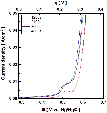
Fig. 1, Table 3은 도금시간을 다르게 하여 제조한 전극의 Zn 침출 전 표면 형상과 성분을 나타내었다. 도금시간은 표면 형상에 큰 영향을 주지 않은 것을 확인할 수 있었으며, 표면 성분의 Ni, Zn 및 Fe의 함량비 또한 비슷한 수준으로 전착되었다. 선행연구 된 Raney Ni 전극의 경우 도금층 두께를 증가시킴으로써 과전압을 줄일 수 있었으며 일정 두께 이상에서는 효과가 크지 않았다. 이러한 현상은 도금층이 일정 두께 이상 두꺼워지면 평탄화 현상에 의해 오히려 일부 표면의 활성사이트를 차단시켜 활성이 감소한 것으로 보고된 바 있다24-26). Fig. 2는 도금시간에 따라 제조한 전극의 산소발생 반응 과전압을 선형주사전위법을 이용해 얻은 결과이다. 도금시간이 증가함에 따라 도금두께의 차이로 인해 산소발생 반응 과전압이 감소하였으며 일정 시간 이후에는 과전압이 증가하였으며 이는 선행 연구와 일치하는 결과를 나타냈다. 과전압은 도금을 40분 진행하여 제조한 전극이 305 mV로 가장 낮았다.
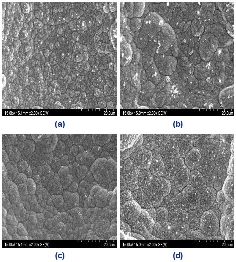
SEM images of electrodeposited Ni-Zn-Fe on Ni foam in Bath(A) with different deposit time of (a) 1,200s, (b) 2,400s, (c) 3,600s, and (d) 4,800s as prepared – ×2,000
3.2 Raney Ni-Zn-Fe 전극 제조 과정에서 도금전류밀도의 영향
도금전류밀도를 변수로 산소발생 반응에 미치는 영향을 확인하기 위하여 전하량은 일정하도록 도금시간을 조절하여 도금을 진행하였다.
Fig. 3은 도금전류밀도에 따라 제조한 전극의 dealloying 전, 후 표면을 SEM 분석을 통해 비교한 사진이다. Fig. 3(a), (c), (e)는 도금전류밀도가 증가함에 따라 전착되는 표면형상이 달라지는 것을 볼 수 있다. 특히 도금전류밀도가 160, 320 mA/cm2로 증가함에 따라 표면은 콜리플라워 모양의 입자가 생성되며 울퉁불퉁한 표면이 생성되는 것을 확인하였다. 이러한 현상은 도금전류밀도가 증가할수록 전극 표면의 Ni 이온의 소비가 전해질로부터 확산 속도보다 빠르기 때문에 국부적인 결정 성장을 촉진한 결과로 설명된다. 또한 도금전류밀도의 증가는 핵형성 속도를 증가시켜 표면에 더 작은 입자사이즈 형성에 영향을 미친다는 연구 결과가 있다27,28).

SEM images of electrodeposited Ni-Zn-Fe on Ni foam in Bath (A) with different current density of 80 mA/cm2, 160 mA/cm2, 320 mA/cm2 (a), (c), and (e) as prepared (b), (d), and (f) after dealloying –×2,000
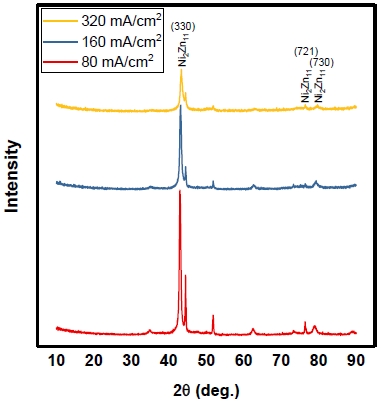
Fig. 4는 도금전류밀도에 따라 제조한 전극의 XRD 데이터이며 Scherrer 방정식을 이용해 입자사이즈를 계산하였다. 입자사이즈는 (330)면에서 측정하였으며 도금전류밀도가 증가할수록 각 15.4986, 13.7495, 7.6626 nm로 감소하였고 도금전류밀도는 입자사이즈 크기에 영향을 주는 것을 확인하였다.
Fig. 5는 제조한 전극의 단면의 line scanning 사진이다. 제조한 전극은 층상 구조로 전착된 것을 확인할 수 있다. 이러한 현상은 Zn 상의 반복적인 저전위 전착(underpotential deposition)에 의한 것으로 추정된다. 이는 환원전위가 낮은 Zn (-0.76 V vs. SHE)의 전착이 먼저 진행되며 그 후에 Ni (-0.26 V vs. SHE) 및 Fe (-0.45 V vs. SHE)의 전착이 이루어지며 층상 구조로 전착되는 현상으로 보고하고 있다29). 또한 도금층에 균열이 확인되며 이는 도금전류밀도가 한계전류밀도 이상으로 높아지면서 도금전류의 일부가 수소 발생에 사용되어 생성된 수소기체에 의해 결정의 성장이 방해받아 층 사이에 공극이 생성된 것으로 판단된다30).

Line scanning of cross section of electrodeposited Ni-Zn-Fe on Ni foam in Bath (A) with different current density of (a) 80 mA/cm2, (b) 160 mA/cm2, and (c) 320 mA/cm2 as prepared – ×2,000
Table 4는 제조한 전극의 dealloying 전, 후 표면 성분 EDS를 나타낸 것이다. 모든 전극에서 환원전위가 낮은 Zn의 함량이 가장 높은 것을 알 수 있으며 Zn의 저전위 전착이 일어난 것이라고 판단한다. 또한 도금전류밀도가 증가할수록 Zn의 함량이 적어지는 것을 확인하였으며, 도금전류밀도는 Zn의 저전위 증착을 억제하는 데 영향을 주는 것으로 판단하였다. Zn의 저전위 증착현상은 Fig. 5에서도 확인할 수 있다. 80 mA/cm2로 도금한 전극의 경우 Zn의 초기 전착량이 다른 금속보다 많은 것을 확인할 수 있으며 도금전류밀도가 증가할수록 Zn의 양은 줄어드는 것을 확인하였다.

Composition of electrodeposited Ni-Zn-Fe on Ni foam in Bath (A) as prepared and after dealloying [atomic%]
Fig. 6은 도금전류밀도에 따라 제조한 전극의 RSA 값을 나타내었다. 도금 과정을 거치지 않은 Ni foam 기판의 RSA 값을 기준으로 하였으며, RSA 값은 도금전류밀도가 높을수록 커지는 경향을 볼 수 있었다. 이러한 이유는 Fig. 3에서 비교적 균열이 적어보이는 (d), (f) 전극을 확대하여 Fig. 7에 나타내었다. 높은 도금전류밀도를 이용하여 제조한 전극의 경우 미세한 균열이 다수 관찰되며 이러한 균열로 인해 도금전류밀도가 높을수록 RSA 값이 증가하였다고 판단한다. 또한 Fig. 3에서 확인한 콜리플라워 형상으로 인한 영향과 Fig. 4에서 dealloying에 의한 다수의 균열에 의해 비표면적이 증가하였으며, Table 4의 EDS 결과를 통해 산소발생 반응 활성에 영향을 주는 Ni 및 Fe의 함량의 증가로 인한 것이라 사료된다.
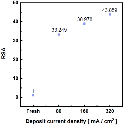
Real surface area of electrodeposited Ni-Zn-Fe on Ni foam in Bath (A) with different current density
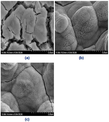
SEM images of electrodeposited Ni-Zn-Fe on Ni foam in Bath (A) with different current density of (a) 80 mA/cm2, (b) 160 mA/cm2 and (c) 320 mA/cm2 after dealloying – ×2,000
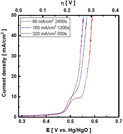
Pérez-Alonso 등31)의 연구에 의하면 Ni-Fe/foam 전극은 Fe 함량에 따라 산소발생 반응 활성이 다르며 Fe가 전극에 약 20-30 wt.% 함유되었을 때 과전압이 가장 낮다고 보고하였다. 각 도금전류밀도를 이용하여 제조한 전극의 산소발생 반응 과전압은 선형주사전위법을 이용하여 결과를 얻어 Fig. 8에 나타내었다. 50 mA/cm2 에서 산소발생 반응 과전압은 320 mA/cm2의 도금전류밀도를 이용하여 제조한 전극이 268 mV로 가장 낮다. 높은 도금전류밀도로 제조한 전극은 콜리플라워 형태의 전착과 dealloying의 효과로 RSA 값이 증가하였고, Ni-Zn-Fe 합금에서 산소발생 반응 활성에 영향을 주는 Ni 및 Fe의 함량비가 증가하여 산소발생 반응 과전압이 감소하였다고 사료된다.
3.3 Raney Ni-Zn-Fe 전극 제조 과정에서 지지체의 영향
지지체의 구조나 형상의 변화에 따른 도금특성과 제조한 전극의 산소발생 반응 특성을 확인하고자 하였다. Ni plate 기판에 Bath (A)에서 같은 전기도금 조건을 이용하여 Raney Ni-Zn-Fe 전극을 제조하였다.
Fig. 9를 보면 Ni plate 기판의 경우 80 mA/cm2 전극에서 콜리플라워 형태로 전착되며 전류밀도가 증가할수록 형태가 뚜렷해지는 것을 확인할 수 있다. Fig. 3의 Ni Foam 기판에 전착한 경우 80 mA/cm2 전극에서는 콜리플라워 형태는 보이지 않으며 넓게 분포되어 있는 것을 볼 수 있다. 하지만 도금전류밀도가 증가하였을 때 콜리플라워 구조가 보이기 시작한다. 이는 Ni foam 기판과 Ni plate 기판에 같은 도금전류밀도를 이용하여 도금하여도 Ni foam 기판은 넓은 표면적에 의해 실제 전극에 가해지는 도금전류밀도는 낮기 때문에 나타나는 전착 특성으로 판단한다32).
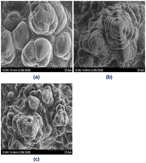
SEM image of electrodeposited Ni-Zn-Fe on Ni plate in Bath (A) with different current density of (a) 80 mA/cm2, (b) 160 mA/cm2, and (c) 320 mA/cm2 as prepared – ×2,000
또한 Table 5의 전착된 성분의 함량은 Table 4에 비해 Fe의 함량 변화가 적은 것을 확인할 수 있다. 이는 Ni foam 기판이 다공성 구조로 되어있어 내부에 Ni 및 Zn 성분이 도금되며 표면에 물질전달속도의 한계 때문에 높은 도금전류밀도에서 Fe의 전착량이 상대적으로 증가하였다고 사료된다.
Ni plate에 도금하기 전, 후의 RSA를 측정하여 Fig. 10에 나타내었다. RSA의 기준값은 도금하기 전 Ni plate 기판을 기준으로 하였다. RSA 값은 도금전류밀도가 높을수록 커지는 경향을 확인하였다. 이는 Ni foam 기판과 같은 특징으로 콜리플라워 형태로 전착되어 표면적을 증가시켰기 때문에 RSA 값이 증가하였다고 판단한다.

Real surface area of electrodeposited Ni-Zn-Fe on Ni plate in Bath (A) with different current density
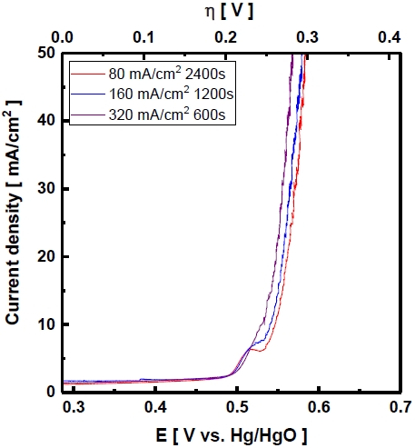
Fig. 11은 Ni plate 기판에 도금전류밀도에 따라 제조한 Ni-Zn-Fe 전극의 과전압을 나타내었다. 320 mA/cm2 전극에서 과전압은 0.281 V의 값을 나타내며 Fig. 8의 과전압과 비교하여 기판에 따른 과전압은 비슷한 값을 가지며 같은 조건으로 도금하여 사용하여도 성능은 비슷하다는 것을 확인하였다.
4. 결 론
본 연구에서는 알칼라인 수전해용 전극의 산소발생 반응 과전압을 낮추기 위해 Ni foam 기판에 Ni-Zn-Fe 합금을 도금하여 전극을 제조하고 물리화학적, 전기화학적 특성을 분석하였다. 또한 도금변수가 산소발생 반응에 미치는 영향을 고찰하였다.
1) 도금시간을 변수로 두어 전극을 제조한 경우 전극의 표면의 형상이나 성분에는 큰 변화가 나타나지 않았으며 전하량에 의해 도금량이 증가하여 산소발생 반응의 과전압 감소에 일부 영향을 주었다. 하지만 본 실험에서는 도금전류밀도가 80 mA/cm2 인 경우, 40분보다 오래 도금하여도 활성에는 큰 영향이 없었다.
2) 도금전류밀도에 따라 전착되는 전극 표면의 입자 형상이 달라지며, 활성에 영향을 미치는 Ni, Fe의 함량이 변하였다. 이러한 전극의 특성의 변화로 인해 도금전류밀도가 320 mA/cm2로 제조한 전극의 산소발생 반응 과전압은 0.268 V로 가장 낮았다.
3) 기판의 형태와 구조에 따라 전극에 전착되는 표면 형상과 조성에 차이를 보였다. 이러한 특성은 Ni foam 기판이 다공성 구조로 비표면적이 넓어 실제 가해지는 도금전류가 Ni plate에 비해 낮기 때문에 나타난 차이라고 판단한다. 하지만 기판에 따른 산소발생 반응 과전압에는 큰 영향이 없는 것으로 판단된다.
4) 산소발생 반응은 느린 반응속도로 인하여 비표면적에 의한 활성증가의 영향은 미비한 것으로 나타나며 표면 형상 및 조성이 활성에 영향을 미치는 것으로 사료된다.
Acknowledgments
본 연구는 2019년도 지식경제부 재원으로 한국에너지 기술평가원(KETEP)의 지원을 받아 수행한 연구 과제이다(No. 20173030041350).
References
-
A. Schavan, “Germany's energy research plan”, Science, Vol. 330, No. 6002, 2010, pp. 295.
[https://doi.org/10.1126/science.1198075]

-
P. Milan, M. Wächter, and J. Peinke, “Turbulent character of wind energy”, Phys. Rev. Lett., Vol. 110, 2013, pp. 138701.
[https://doi.org/10.1103/PhysRevLett.110.138701]

-
A. Woyte, R. Belmans, and J. Nijs, “Fluctuations in instantaneous clearness index: analysis and statistics”, Solar Energy, Vol. 81, No. 2, 2007, pp. 195-206.
[https://doi.org/10.1016/j.solener.2006.03.001]

-
L. Bi, S. Boulfrad, and E. Traversa, “Steam electrolysis by solid oxide electrolysis cells (SOECs) with proton-conducting oxides”, Chem. Soc. Rev., Vol. 43, No. 24, 2014, pp. 8255-8270.
[https://doi.org/10.1039/C4CS00194J]

-
M. Wang, Z. Wang, X. Gong, and Z. Guo, “The intensification technologies to water electrolysis for hydrogen production – a review”, Renewable and Sustainable Energy Reviews, Vol. 29, 2014, pp.573-588.
[https://doi.org/10.1016/j.rser.2013.08.090]

-
K. Zeng and D. Zhang, “Recent progress in alkaline water electrolysis for hydrogen production and applications”, Prog. Energy Combust. Sci., Vol. 36, No. 3, 2010, pp. 307–326.
[https://doi.org/10.1016/j.pecs.2009.11.002]

-
D. M. F. Santos, C. A. C. Sequeira, and J. L. Figueiredo, “Hydrogen production by alkaline water electrolysis”, Quim. Nova, Vol. 36, No. 8, 2013, pp. 1176-1193.
[https://doi.org/10.1590/S0100-40422013000800017]

-
O. Schmidt, A. Gambhir, I. Staffell, A. Hawkes, J. Nelson, and S. Few, “Future cost and performance of water electrolysis: an expert elicitation study”, Int. J. Hydrogen Energy, Vol. 42, No. 52, 2017, pp. 30470-30492.
[https://doi.org/10.1016/j.ijhydene.2017.10.045]

-
M. Gong and H. Dai, “A mini review of NiFe-based materials as highly active oxygen evolution reaction electrocatalysts”, Nano Res., Vol. 8, No. 1, 2015, pp. 23-39.
[https://doi.org/10.1007/s12274-014-0591-z]

-
B. S. Yeo and A. T. Bell, “Enhanced activity of gold-supported cobalt oxide for the electrochemical evolution of oxygen”, J. Am. Chem. Soc., Vol. 133, No. 14, 2011, pp. 5587-5593.
[https://doi.org/10.1021/ja200559j]

-
V. Vij, S. Sultan, A. M. Harzandi, A. Meena, J. N. Tiwari, W. G. Lee, T. Yoon, and K. S. Kim, “Nickel-based electrocatalysts for energy-related applications: oxygen reduction, oxygen evolution, and hydrogen evolution reactions”, ACS Catal., Vol. 7, No. 10, 2017, pp. 7196-7225.
[https://doi.org/10.1021/acscatal.7b01800]

-
S. M. Fernández-Valverde, E. Ordoñez-Regil, G. Cabañas-Moreno, and O. Solorza-Feria, “Electrochemical behavior of Ni-Mo electrocatalyst for water electrolysis”, J. Mex. Chem. Soc., Vol. 54, No. 3, 2010, pp. 169-174.
[https://doi.org/10.29356/jmcs.v54i3.931]

-
J. Kubisztal and A. Budniok, “Study of the oxygen evolution reaction on nickel-based composite coatings in alkaline media”, Int. J. Hydrogen Energy, Vol. 33, No. 17, 2008, pp. 4488-4494.
[https://doi.org/10.1016/j.ijhydene.2008.06.023]

-
D. A. Corrigan and R. M. Bendert, “Effect of coprecipitated metal ions on the electrochemistry of nickel hydroxide thin films: cyclic voltammetry in 1M KOH”, J. Electrochem. Soc., Vol. 136, No. 3, 1989, pp. 723-728.
[https://doi.org/10.1149/1.2096717]

-
B. K. Kim, S. K. Kim, S. K. Cho, and J. J. Kim, “Enhanced catalytic activity of electrodeposited Ni-Cu-P toward oxygen evolution reaction”, Appl. Catal. B, Vol. 237, 2018, pp. 409-415.
[https://doi.org/10.1016/j.apcatb.2018.05.082]

-
X. Li, F. C. Walsh, and D. Pletcher, “Nickel based electrocatalysts for oxygen evolution in high current density, alkaline water electrolysers”, Phys. Chem. Chem. Phys., Vol. 13, No. 3, 2011, pp. 1162-1167.
[https://doi.org/10.1039/C0CP00993H]

-
M. S. Burke, L. J. Enman, A. S. Batchellor, S. Zou, and S. W. Boettcher, “Oxygen evolution reaction electrocatalysis on transition metal oxides and (Oxy)hydroxides: activity trends and design principles”, Chem. Mater., Vol. 27, No. 22, 2015, pp. 7549-7558.
[https://doi.org/10.1021/acs.chemmater.5b03148]

- B. Zeifert, J. S. Blasquez, J. G. C. Moreno, and H. A. Calderón, “Raney-Nickel catalysts produced by mechanicl alloying”, Rev.Adv.Mater.Sci., Vol. 18, 2008, pp. 632-638. Retrieved from https://www.researchgate.net/profile/Jose_Cabanas-Moreno/publication/267301499_Raney-nickel_catalysts_produced_by_mechanical_alloying/links/545454a40cf26d5090a55b16.pdf, .
-
E. Endoh, H. Otouma, T. Morimoto, and Y. Oda, “New Raney nickel composite-coated electrode for hydrogen evolution”, Int. J. Hydrogen Energy, Vol. 12, No. 7, 1987, pp. 473-479.
[https://doi.org/10.1016/0360-3199(87)90044-9]

-
G. Sheela, M. Pushpavanam, and S. Pushpavanam, “Zinc–nickel alloy electrodeposits for water electrolysis”, Int. J. Hydrogen Energy, Vol. 27, No. 6, 2002, pp. 627-633.
[https://doi.org/10.1016/S0360-3199(01)00170-7]

-
R. Phillips and C. W. Dunnill, “Zero gap alkaline electrolysis cell design for renewable energy storage as hydrogen gas”, RSC Advances, Vol. 6, No. 102, 2016, pp. 100643-100651.
[https://doi.org/10.1039/C6RA22242K]

-
R. K. Shervedani and A. Lasia, “Evaluation of the surface roughness of microporous Ni–Zn–P electrodes by in situ methods”, J. Appl. Electrochem., Vol. 29, No. 8, 1999, pp. 979-986.
[https://doi.org/10.1023/A:1003577631897]

-
M. Lukaszewski, M. Soszko, and A. Czerwinski, “Electrochemical methods of real surface area determination of noble metal electrodes – an overview”, Int. J. Electrochem. Sci., Vol. 11, 2016, pp. 4442-4469.
[https://doi.org/10.20964/2016.06.71]

-
A. T. Swesi, J. Masud, and M. Nath, “Nickel selenide as a high-efficiency catalyst for oxygen evolution reaction”, Energy & Environmental Science, Vol. 9, No. 5, 2016, pp. 1771-1782.
[https://doi.org/10.1039/C5EE02463C]

-
N. Todoroki and T. Wadayama, “Oxygen reduction and oxygen evolution reaction activity on Co/Pt(111) surfaces in alkaline solution”, The Electrochemical Society, Vol. 86, No. 13, 2018, pp. 569-574.
[https://doi.org/10.1149/08613.0569ecst]

- W. B. Han, H. S. Cho, W. C. Cho, and C. H. Kim, “Understanding the effect on hydrogen evolution reaction in alkaline medium of thickness of physical vapor deposited Al-Ni electrodes”, Trans. of The Korean Hydrogen and New Energy Society, Vol. 28, No. 6, 2017, pp. 610-617.
-
Z. Feng, Q. Li, J. Zhang, P. Yang, and M. An, “Electrochemical behaviors and properties of Zn-Ni alloys obtained from alkaline non-cyanide bath using 5,5'-dimethylhydantoin as complexing agent”, J. Electrochem. Soc., Vol. 162, No. 9, 2015, pp. 412-422.
[https://doi.org/10.1149/2.0121509jes]

-
J. Wang, G. D. Wilcox, R. J. Mortimer, C. Liu, and M. A. Ashworth, “Electrodeposition and characterisation of novel Ni-NbOx composite coatings as a diffusion barrier for liquid solder interconnects - part II: diffusion barrier performance”, ECS Transactions, Vol. 64, No. 40, 2015, pp. 109-121.
[https://doi.org/10.1149/06440.0109ecst]

-
C. Srivastava, S. K. Ghosh, S. Rajak, A. K. Sahu, R. Tewari, V. Kain, and G. K. Dey, “Effect of pH on anomalous co-deposition and current efficiency during electrodeposition of Ni-Zn-P alloys”, Surf. Coat. Technol., Vol. 313, 2017, pp. 8-16.
[https://doi.org/10.1016/j.surfcoat.2017.01.043]

- J. H. Park, “Characterization of mechanical property of ni metal mask fabricated by electroforming with different current densities”, Master thesis, Sungkyunkwan University, Seoul, Korea, 2010. Retrieved from http://m.riss.kr/search/detail/DetailView.do?p_mat_type=be54d9b8bc7cdb09&control_no=62c9dc6853edb1e9ffe0bdc3ef48d419, .
-
F. J. Pérez-Alonso, C. Adán, S. Rojas, M. A. Peña, and J. L. G. Fierro, “Ni/Fe electrodes prepared by electrodeposition method over different substrates for oxygen evolution reaction in alkaline medium”, Int. J. Hydrogen Energy, Vol. 39, No. 10, 2014, pp. 5204-5212.
[https://doi.org/10.1016/j.ijhydene.2013.12.186]

- T. K. Lee, J. W. Kim, K. K. Bae, C. S. Park, K. S. Kang, Y. H. Kim, and S. U. Jung, “Study on oxygen evolution reaction of Ni-Zn-Fe electrode for alkaline water electrolysis”, Trans. of The Korean Hydrogen and New Energy Society, Vol. 29, No. 6, 2018, pp. 549-558.
