Characterization for Performance of Zn-Air Recharegeable Batteries on Different Composition in Acidic Electrolyte
2021 The Korean Hydrogen and New Energy Society. All rights reserved.
Abstract
The combination of different concentrations of ZnSO4 in acidic solution as electrolyte in Zn-air batteries was investigated by Zn symmetrical cell test, half-cell and full cell tests. Using 1 M ZnSO4 + 0.05 M H2SO4 as electrolyte and MnO2 as air cathode catalyst with Zn foil anode, this combination had a satisfactory performance with balance of electrochemical activity and stability. Its electrochemical activity was matched to or even better than the PtRu catalyst in different current density. And its cycle life was improved (more than 100 cycles stable) by suppressing the growth of zinc dendrites on anode obviously. This electrolyte overcame the shortcomings of alkaline electrolyte that are easy to react with CO2 in the air, severely growth of Zn dendrites caused by uneven plating/stripping of Zn.
Keywords:
Oxygen reduction, Oxygen evolution, Catalyst, Air electrode, Zn-air battery키워드:
산소환원, 산소발생, 촉매, 공기극, 아연공기전지1. Introduction
Most Zn-air batteries are using alkaline solution as electrolyte, such as KOH and NaOH, in order to ensure the high activity of both the Zn anode and air cathode1-5). Though the electrochemistry of Zn in alkaline electrolytes is easily reversible, the alkaline solution can react with CO2 of atmosphere to form carbonate or bicarbonate, this will decrease the electrolyte conductivity. The formed carbonate and bicarbonate are precipitated in the pores of the air electrodes, and this also make negative affect on the performance of air electrodes and batteries, because of the high solubility of its discharge product i.e. zincate in alkaline electrolytes. Upon recharging, the reluctance of zincate to fully return to the same location at the electrode surface triggers electrode shape change or dendritic growth by Zn deposition (Fig. 1), which gradually degrade the battery performance. Due to the dendrite growth of Zn, the surface of the anode increases and this causes an increase in the surface area. Therefore, the corrosion and other surface reactions are accelerated. More seriously, the dendrites will pierce the separator and the batteries will have a sudden short circuit. Hence, dendrite growth is one of the key obstacle factors influencing the cycle life of batteries, and the life time problem of rechargeable Zn-air batteries limit their commercial application. How to inhibit the growth of the dendrites in rechargeable Zn-air batteries has always been a challenge for researchers.

Schematic diagrams of Zn dendrite growth in KOH with Zn2+ salt (left) and ZnSO4 with H2SO4 (right) solution
Many strategies have been used to suppress the Zn dendrite growth on the anode. Such as changing the structure of the electrode, addition of additives to the electrolyte to modify the deposition characteristics6,7), and protecting the layer of the Zn metal anode by surface coating8-10). An effective method is using Ni(OH)2 as a counter electrode, meantime, through a 3-dimensional Zn sponges to force Zn deposited on the backside of the Zn sponges11,12). However, because of the complicated process and high cost, there is almost no possibility of large-scale application of this technology. To the best of our knowledge, there is no method that can balance effectiveness, convenience and economy until now. And, most literature regarding dendrite elimination have been focusing in alkaline electrolyte. There is little knowledge about dendrite suppression for secondary Zn batteries using neutral or mild acidic media as electrolytes. In addition, the shortcomings of the alkaline electrolyte mentioned above also need to be overcome, this makes the technical difficulty significantly increased. Recently, many researchers have paid attention to near-neutral and acidic aqueous electrolytes to suppress the dendrites growth and improve electrochemical performance in Zn ion batteries13-15). But relevant research on Zn-air batteries in neutral and acidic aqueous electrolytes is still blank.
In this work, we developed a weak acid electrolyte, different concentration ZnSO4 & H2SO4 used as electrolyte in Zn-air rechargeable batteries and it exhibits a high cycle life by suppressing the growth of Zn dendrites (Fig. 2), while maintaining relatively satisfactory activity.
2. Experimental
Zn foil (0.01 in thick, 99.98%), Zn wire (a diameter of 1.0 mm, 99.95%) and Pt mesh were obtained from Alfa Aesar Co., Korea. MnO2 flakes and zinc sulfate heptahydrate (ZnSO4 · 7H2O, 99%) were purchased from Samchun Chemicals, Korea. Sulfuric acid (H2SO4, 95%) was purchased from Duksan pure chemicals Co., Korea. For comparison, PtRu/carbon electrode (Fuel cell store, 2.0 mg/cm2) was used. All chemicals were used as received without further purification. The electrolytes were prepared by dissolving the calculated amount of ZnSO4 and/or H2SO4 into deionized water.
In symmetric cell test, Zn foil was used as anode and cathode, and the different concentration of ZnSO4 & H2SO4 as electrolyte solution. Galvanostatic Zn deposition/dissolution investigations were done using a battery tester (WBCS3000, WonATech Co. Ltd., Seoul, Korea) at room temperature with different current density. Every cycle was consisted of 1 hour charging process and 1 hour discharging process.
The half-cell test of cathode for oxygen reduction reaction (ORR) and oxygen evolution reaction (OER) was conducted in the prepared solution using a three-electrode system. The working electrode was cut into a round shape which area is 1cm2. The counter and reference electrodes were used a Pt mesh and a Zn wire, respectively. The linear sweep voltammetry (LSV) was conducted to measure current according to cell potential using a potentiostat/galvanostat. The cell potential was scanned at a scan rate of 1mV/s for 20 times between 0.5 and 2.4 V (vs. Zn/Zn2+), which were assigned to -0.263 and 1.637 V vs. a standard hydrogen electrode (SHE). The charge/discharge test of the catalysts was carried out at certain current16). Every cycle was consisted of 1 hour charging process and 1 hour discharging process. The tests were conducted and recorded using a potentiostat/galvanostat.
In the full cell test, Zn foil was used as anode, MnO2 or PtRu/C was used as cathode, and electrolyte was 1.0 M ZnSO4 + 0.05 M H2SO4. Galvanostatic charge/discharge investigations were done using a battery tester at room temperature in different current density. Every cycle was consisted of 1 hour charging process and 1 hour discharging process.
The XRD patterns were characterized by the X-ray diffractometer produced by PANalytical Corporation. The X-ray source is using a Cu-Kα (λ = 0.15406 Å), and the operating voltage was 40 kV, the operating current was 100 mA, the scanning range 2θ was 10° to 90°. Scanning electron microscope (Hitachi SU8220) was used to analyze the surface morphology and the particle size of the sample.
3. Results and discussion
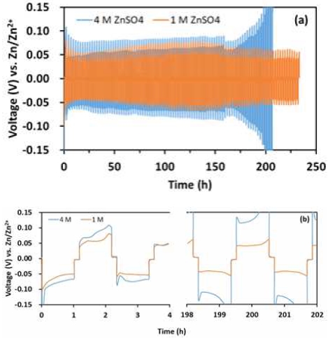
To investigate the electrochemical performance of Zn plating/stripping, the Zn//Zn symmetrical cell was assembled. As shown in Fig. 2(a), the voltage of the cell which use 1.0 M ZnSO4 as electrolyte toggles within a narrow voltage range (-0.06 mV) at 2.0 mA/cm2, and it can maintain stability for more than 230 hours. The cell has the characteristics of highly stable, less polarized, and highly reversible Zn deposition/dissolution. However, using 4.0 M ZnSO4 as electrolyte, the cell reached the cut-off threshold near 200 h and the polarization potential increased rapidly. Compared with 1.0 M ZnSO4, there was a significant gap in stability. The polarization potential drop in a symmetrical cell in using 1.0 M ZnSO4, as shown in Fig. 2(b), which may be ascribed to the resistive losses across the cell from a uniform and stable Zn deposition/dissolution17,18).
Fig. 3 shows the SEM images of the Zn foil after 100 plating/stripping cycles in 4.0 M and 1.0 M ZnSO4 electrolyte. The surface of fresh Zn foil was flat and smooth with some defects (holes), which may be produced during manufacturing process. In Fig. 3(b) which is showing the surface of Zn foil cycled 100 times in 4.0 M ZnSO4 electrolyte, some large-scale plate-like structure was observed on the surface, and lots of vertical-like structured morphology indicating formation of Zn dendrites on the surface. While the cell was cycled in 1.0 M ZnSO4 electrolyte (Fig. 3[c]), the Zn surface was relatively uniform, with only a few plate-like structure materials dotted on the surface. Fig. 4 shows the current-potential curves of PtRu/C between 0.5 and 2.4 V of 20th cycle for the ORR and OER by LSV in 1 M ZnSO4, 1M ZnSO4 + 0.1 M H2SO4 and 1 M ZnSO4 + 0.5 M H2SO4. From the figure, it clearly shows that the cell at higher concentration of acid has better ORR & OER performance than in 1M ZnSO4 electrolyte. This means that neutral or low acid solutions give low ORR and OER performance. However, in electrolyte containing above 0.5 M H2SO4, we found severe hydrogen evolution at Zn anode. So, lower concentration of H2SO4 than 0.5 M H2SO4 was adopted for next experiment.
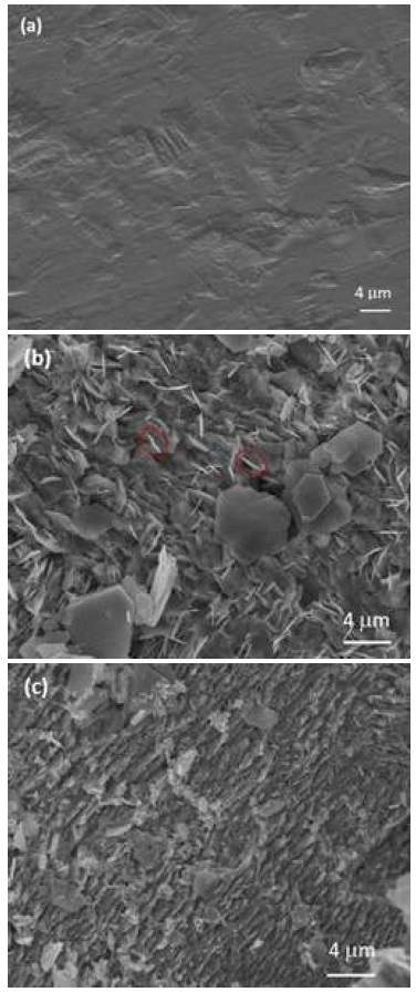
SEM images of surface of Zn foils for 100 plating/stripping cycles, (a) fresh Zn foil, (b) using 4.0 M ZnSO4, and (c) 1.0 M ZnSO4
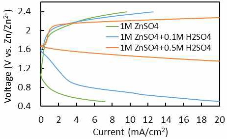
Current-voltage profiles of PtRu/C for ORR and OER at 20th cycle by linear sweep voltammetry in 0.5 M H2SO4 and 1.0 M ZnSO4 + 0.5 M H2SO4
Fig. 5 shows the galvanostatic Zn plating/stripping in a symmetrical cell at 2 mA/cm2 of current density in different electrolytes. In the symmetrical cell tests, the cell potentials in all electrolytes were stable. Between them, the cell using 1.0 M ZnSO4 + 0.05 M H2SO4 as electrolyte has the best performance with the smallest voltage gap and lowest voltage change rate (Table 1). There is little difference between 1.0 M ZnSO4 + 0.005 M H2SO4 and 1.0 M ZnSO4 + 0.0005 M H2SO4 samples. The order of their performance is as follows: 1.0 M ZnSO4 + 0.05 M H2SO4 > 1.0 M ZnSO4 + 0.005 M H2SO4 > 1.0 M ZnSO4 + 0.0005 M H2SO4.
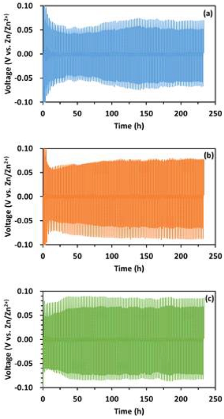
Galvanostatic Zn deposition/dissolution in a symmetrical cell at 2 mA/cm2 current density in different electrolytes. (a) 1.0 M ZnSO4 + 0.05 M H2SO4, (b) 1.0 M ZnSO4 + 0.005 M H2SO4, (c) 1.0 M ZnSO4 + 0.0005 M H2SO4
SEM images of the Zn after 100 plating/stripping cycles in different electrolyte are shown in Fig. 6 In 1.0 M ZnSO4 + 0.05 M H2SO4 electrolyte, Zn surface was covered by plate-like structure material that size is around 10 nm. And vertical-like structured morphology material was observed on the surface. In 1.0 M ZnSO4 + 0.005 M H2SO4 electrolyte, the size of plate-like structure material was obviously increased to around 20-30nm. Lots of vertical-like structured morphology material has also begun to appear. While in 1.0 M ZnSO4 + 0.0005 M H2SO4 electrolyte, the size of material on the surface was decreased to below 10 nm, but vertical-like structured material also appeared in large numbers. The Zn surface cycled in 1.0 M ZnSO4 + 0.05 M H2SO4 was uniform compared with the other electrolytes.
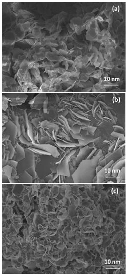
SEM images of the Zn after 100 plating/stripping cycles in different electrolytes. (a) 1.0 M ZnSO4 + 0.05 M H2SO4, (b) 1.0 M ZnSO4 + 0.005 M H2SO4, (c) 1.0 M ZnSO4 + 0.0005 M H2SO4
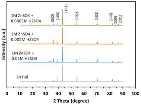
XRD results of the Zn anode electroplated after 100 cycles in different electrolytes are shown in Fig. 7. According to the XRD results, the Zn crystals grow in various orientations. For all samples, the highest intensity peak is around at 42°, indicating the Zn growth in (101) orientation. The other significant planes are (002), (100), (102), (103), (112), (200), and (201). In order to facilitate comparison, the peak intensities of all patterns are normalized, taking the intensity of the (101) peak as the reference. Compared with fresh Zn foil, the peak intensity of the (002) and (103) plane were enhanced, while peaks at (100) and (102) plane were weak. This means using 1.0 M ZnSO4+0.05 M H2SO4 electrolyte, the preferential growth on Zn surface has changed from (100) and (102) plane to (002) and (103) plane. The Zn growth on the (100) is perpendicular to the sample surface. However, the crystal growth on the (103) plane is nearly horizontal with the electrode surface, thus dendrites are much less likely to form on the (103) plane6,19). Moreover, Zn metal with exposed (002) plane has more resistance against dendrite formation while exposed (100) plane is prone to dendrite formation6). It is easy to speculate that the use of this electrolyte will have a better effect of inhibiting the formation of dendrites.
Using 1.0 M ZnSO4 + 0.005 M H2SO4 as electrolyte, the obvious changes in XRD results are preferential growth on Zn surface from (100) plane to (002) plane. According to the previous analysis, it also has the ability to inhibit the growth of Zn dendrites, but it is not as good as the 1.0 M ZnSO4 + 0.05 M H2SO4 because it has only (002) plane enhanced, the (103) plane is same with fresh Zn foil. For 1.0 M ZnSO4 + 0.0005 M H2SO4 electrolyte, nearly all peaks are weaker than the fresh Zn foil. In other words, it enhances the Zn growth only in one orientation of (101) plane. The dendrites were grown on the (101) plane with -70° to the surface of the electrode6,15). This makes it has less effect in inhibiting the growth of dendrites. These results are consistent with the symmetrical cell test.
Fig. 8 shows the galvanostatic Zn plating/stripping in a symmetrical cell in 1.0 M ZnSO4 + 0.05 M H2SO4 as electrolyte at different current densities (2-10 mA/cm2). It can be clearly seen that as the current density increases, the potential also increases. At 2 mA/cm2 of current density, it had a narrow potential gap and performance in stability was very stable. When current density increased to 5 mA/cm2, the potential gap slightly increased comparing with 2 mA/cm2, but its stability has not changed significantly, as shown in Table 2. However, at high current density, 10 mA/cm2, the voltage has wave-like fluctuations. The possible reason may be that under this condition, the side reaction of Zn under acidic conditions by self-corrosion is accelerated, and the generated hydrogen periodically accumulates and desorbs on the Zn surface, resulting in voltage fluctuations.
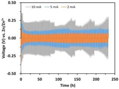
Galvanostatic Zn plating/stripping in a symmetrical cell in 1.0 M ZnSO4 + 0.05 M H2SO4 as electrolyte at different current density

Summary of galvanostatic Zn deposition/dissolution for symmetrical cell test in 1.0 M ZnSO4 + 0.05 M H2SO4 as electrolyte at different current density
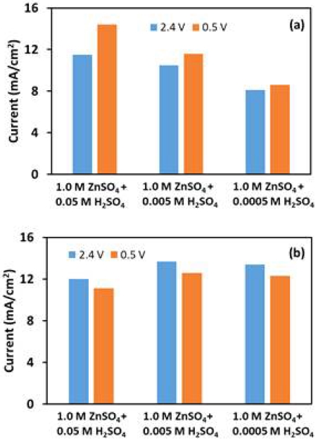
It is widely known that precious metals, especially Pt, are good catalysts for ORR. But it has showed a low performance in OER, because its surface will be passivated during reaction20). Thus, we choose the precious metal catalyst, PtRu/C, and the non-precious metal catalyst, MnO2, for investigation. Fig. 9 shows current density at 20th cycle for ORR and OER by LSV at 0.5 and 2.4 V. For PtRu/C, obviously, the increase in H+ concentration has a certain positive effect on the activity. As the concentration of H+ increases, the activity gradually increases. However, for MnO2 the reduction of H+ concentration has almost no effect on its activity. When using 1.0 M ZnSO4 + 0.05 M H2SO4 as electrolyte, both catalysts showed almost similar activity.
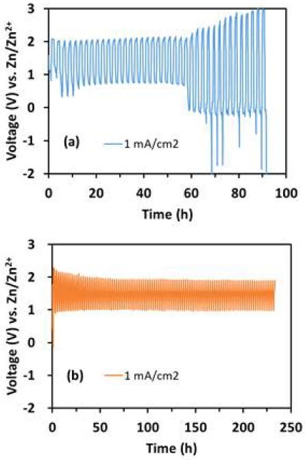
Fig. 10 shows the galvanostatic cell test of Zn/PtRu and Zn/MnO2 in 1.0 M ZnSO4 + 0.05 M H2SO4 as electrolyte at different current density. When current density was 1 mA/cm2, the Zn/MnO2 cell maintained a discharge voltage above 1 V for 100 cycles (over 200 hours). However, the Zn/PtRu cell maintained 0.75 V discharge voltage for nearly to 60 hours, and then the cell voltage continuously increased to 3.0 V for charging and below 0.0 V for discharging.
4. Conclusions
ZnSO4 with H2SO4 as acidic electrolyte in Zn-air rechargeable batteries was investigated. Using 1.0 M ZnSO4 + 0.05 M H2SO4 as electrolyte, and MnO2 as air cathode, this combination showed a good cell performance with the balance of electrochemical activity and cycle life. This electrolyte can greatly increase the cycle life (more than 200 hours stable) by suppressing the growth of dendrites significantly. In this electrolyte, the activity of MnO2 as a cathode is comparable to that of the precious metal PtRu in half cell test. In the full cell test, MnO2 with Zn foil anode showed much better cycle life than using PtRu catalysts as air electrode. This combination overcomes the many shortcomings of using alkaline solutions as electrolytes and has broad application prospects.
Acknowledgments
This work was supported by the Technology Innovation Program of Korea evaluation institute of industrial technology (KEIT) grant funded By the ministry of trade, industry & energy (MOTIE, Korea) (No. 20002425) and the national research foundation of Korea (NRF) grant funded by the Korea government (MSIT) (No. 2021R1I1A3057906).
References
-
M. Chen, L. Wang, H. Yang, S. Zhao, H. Xu, and G. Wu. “Nanocarbon/oxide composite catalysts for bifunctional oxygen reduction and evolution in reversible alkaline fuel cells: a mini review”, J. Power Sources, Vol. 375, 2018, pp. 277-290.
[https://doi.org/10.1016/j.jpowsour.2017.08.062]

-
Z. Huang, J. Wang, Y. Peng, C. Jung, A. Fisher, and X. Wang. “Design of efficient bifunctional oxygen reduction/evolution electrocatalyst: recent advances and perspectives”, Adv. Energy Mater, Vol. 7, No. 23, 2017, pp. 700544.
[https://doi.org/10.1002/aenm.201700544]

-
N. Logeshwaran, S. Ramakrishnan, S.S. Chandrasekaran, M. Vinothkannan, A.R. Kim, S. Sengodan, D.B. Velusamy, P. Varadhan, Jr-H. He, and D.J. Yoo, “An efficient and durable trifunctional electrocatalyst for zinc–air batteries driven overall water splitting”, Appl. Cat. B: Environ, Vol. 297, 2021, pp. 120405.
[https://doi.org/10.1016/j.apcatb.2021.120405]

-
S. Ramakrishnan, J. Balamurugan, M. Vinothkannan, A. R. Kim, S. Sengodan, and D. J. Yoo, “Nitrogen-doped graphene encapsulated FeCoMoS nanoparticles as advanced trifunctional catalyst for water splitting devices and zinc-air batteries”, Appl. Cat. B: Environ. Vol. 279, 2020, pp. 119381.
[https://doi.org/10.1016/j.apcatb.2020.119381]

-
E. Vijayakumar, S. Ramakrishnan, C. Sathiskumar, D. J. Yoo, J. Balamurugan, H. S. Noh, D. Kwon, Y. H. Kim, and H. Lee, “MOF-derived CoP-nitrogen-doped carbon@NiFeP nanoflakes as an efficient and durable electrocatalyst with multiple catalytically active sites for OER, HER, ORR and rechargeable zinc-air batteries”, Chem. Eng. J. Vol 428, 2022, pp. 131115.
[https://doi.org/10.1016/j.cej.2021.131115]

-
K. E. Sun, T. K. Hoang, T. N. L. Doan, Y. Yu, X. Zhu, Y. Tian, and P. Chen, “Suppression of dendrite formation and corrosion on zinc anode of secondary aqueous batteries”, ACS Appl. Mater. Interf, Vol. 9, 2017, pp. 9681-9687.
[https://doi.org/10.1021/acsami.6b16560]

-
J. Yi, P. Liang, X. Liu, K. Wu, Y. Liu, Y. Wang, Y. Xia, and J. Zhang, “Challenges, mitigation strategies and perspectives in development of zinc-electrode materials and fabrication for rechargeable zinc-air batteries”, Energy Environ. Sci, Vol. 11, 2018, pp. 3075-3095.
[https://doi.org/10.1039/C8EE01991F]

-
W. Dong, J. Shi, T. Wang, Y. Yin, C. Wang, ang Y. Guo. “3D Zinc@ carbon fiber composite framework anode for aqueous Zn-MnO2 batteries”, RSC Adv, Vol. 8, No. 32, 2018, pp. 19157-19163.
[https://doi.org/10.1039/C8RA03226B]

-
P. Liang, J. Yi, X. Liu, K. Wu, Z. Wang, J. Cui, Y. Liu, Y. Wang, Y. Xia, and J. Zhang, “Highly reversible Zn anode enabled by controllable formation of nucleation sites for Zn-based batteries”, Adv. Funct. Mater, Vol. 30, No. 13, 2020, pp. 1908528.
[https://doi.org/10.1002/adfm.201908528]

-
L. Kang, M. Cui, F. Jiang, Y. Gao, H. Luo, J. Liu, W. Liang, and C. Zhi, “Nanoporous CaCO3 coatings enabled uniform Zn stripping/plating for long-life zinc rechargeable aqueous batteries”, Adv. Energy Mater, Vol. 8, No. 25, 2018, pp. 1801090.
[https://doi.org/10.1002/aenm.201801090]

-
S. Higashi, S. W. Lee, J. S. Lee, K. Takechi, and Y. Cui, “Avoiding short circuits from zinc metal dendrites in anode by backside-plating configuration”, Nat. Commun, Vol. 7, No. 11801, 2016, pp. 1-6.
[https://doi.org/10.1038/ncomms11801]

-
J. F. Parker, C. N. Chervin, I. R. Pala, M. Machler, M. F. Burz, J. W. Long, and D. R. Rolison, “Rechargeable nickel-3D zinc batteries: an energy-dense, safer alternative to lithium-ion”, Science, Vol. 356, No. 6336, 2017, pp. 415-418.
[https://doi.org/10.1126/science.aak9991]

-
S. J. Banik and R. Akolkar. “Suppressing dendrite growth during zinc electrodeposition by PEG-200 additive”, J. Electrochem. Soc, Vol. 160, No. 11, 2013, pp. D519.
[https://doi.org/10.1149/2.040311jes]

-
H. Li, C. Han, Y. Huang, Y. Huang, M. Zhu, Z. Pei, Q. Xue, Z. Wang, Z. Liu, and Z. Tang, “An extremely safe and wearable solid-state zinc ion battery based on a hierarchical structured polymer electrolyte” Energy Environ. Sci, Vol. 11, No. 4, 2018, pp. 941-951
[https://doi.org/10.1039/C7EE03232C]

-
Z. Kang, C. Wu, L. Dong, W. Liu, J. Mou, J. Zhang, Z. Chang, B. Jiang, G. Wang, and F. Kang, “3D porous copper skeleton supported zinc anode toward high capacity and long cycle life zinc ion batteries. acs sustain. chem” Eng, Vol. 7, No. 3, 2019, pp. 3364-3371.
[https://doi.org/10.1021/acssuschemeng.8b05568]

-
L. Bo, H. R. Rim, H. K. Lee, G. Park, and J. Shim, “Characterization of NiO and Co3O4-doped La(CoNi)O3 perovskite catalysts synthesized form excess Ni for oxygen reduction and evolution reaction in alkaline solution”, Trans Kor Hydrogen New Energy Soc, Vol. 32, No. 1, 2021, pp. 41-52.
[https://doi.org/10.7316/KHNES.2021.32.1.41]

-
B. W. Olbasa, F. W. Fenta, S.-F. Chiu, M.-C. Tsai, C.-J. Huang, B. A. Jote, T. T. Beyene, Y.-F. Liao, C.-H. Wang, and W.-N. Su, “High-rate and long-cycle stability with a dendrite-free zinc anode in an aqueous zn-ion battery using concentrated electrolytes”, ACS Appl. Energy Mater, Vol. 3, No. 5, 2020, pp. 4499-4508.
[https://doi.org/10.1021/acsaem.0c00183]

-
J. F. Parker, C. N. Chervin, E. S. Nelson, D. R. Rolison, and J. W. Long, “Wiring zinc in three dimensions re-writes battery performance- dendrite- free cycling. Energy Environ”, Sci, Vol. 7, No. 3, 2014, pp. 1117-1124.
[https://doi.org/10.1039/C3EE43754J]

-
D. J. Mackinnon, J. M. Brannen, and P. L. Fenn, “Characterization of impurity effects in zinc electrowinning from industrial acid sulphate electrolyte”, J. Appl. Electrochem., Vol. 17, 1987, pp. 1129-1143.
[https://doi.org/10.1007/BF01023596]

-
Y. Li and H. Dai, “Recent advances in zinc-air batteries”, Chem. Soc. Rev, Vol. 43, No. 15, 2014, pp. 5257-5275.
[https://doi.org/10.1039/C4CS00015C]

