PEMFC Based Cogeneration System Using Heat Pump
2021 The Korean Hydrogen and New Energy Society. All rights reserved.
Abstract
In recent years, polymer electrolyte membrane fuel cell (PEMFC) based cogeneration system has received more and more attention from energy researchers because beside electricity, the system also meets the residential thermal demand. However, the low-quality heat exited from PEMFC should be increased temperature before direct use or storage. This study proposes a method to utilize the heat exhausted from a 10 kW PEMFC by coupling a heat pump. Two different configuration using heat pump and a reference layout with heater are analyzed in term of thermal and total efficiency. The system coefficient of performance (COP) increases from 0.87 in layout with heaters to 1.26 and 1.29 in configuration with heat pump and cascade heat pump, respectively. Lastly, based on system performance result, another study in economics point of view is proposed.
Keywords:
Polymer electrolyte membrane fuel cell, Fuel cell, Cogeneration, Heat pump키워드:
고분자 전해질막 연료전지, 연료전지, 열병합, 히트펌프1. Introduction
The proton exchange membrane fuel cell (PEMFC) uses an ion conduction polymer as electrolyte. Each side of the electrolyte is bonded a catalyzed porous electrode1). The PEMFC works at relatively low temperature, typically 50 to 100℃, which allows a quick start. Besides, PEMFC is one of the most developed fuel cells for domestic cogeneration of heat and power (CHP) system because of its low temperature operation and high reliability2). PEMFC based CHP system not only provides a high efficiency electricity conversion, but also manages waste energy properly, leading to a reduction in primary energy use.
During 1960s, the first PEMFC was developed by General Electric in the United States for use by Nasa for their space vehicles1). After many ups and downs over the next 20 years, recently, it has received a lot of attention again. Along with the miracle development of electric vehicles, PEMFC has been studied a lot for use on cars3), buses4), and even boat5). In CHP application, Tokyo Gas firstly introduced their development to Japanese customers in 2005, then its second generation was also successfully launched into the market in 20096).
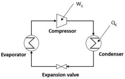
Heat pump system, as shown in Fig. 1, is a system used to bring heat from a low temperature source to higher temperature space7), being the opposite with the direction of natural heat transfer. To measure efficiency of a heat pump system, coefficient of performance (COP), which is the ratio between desired heat output and input work, is used. The heat pump COP formula is described by Eq. 1.
| (1) |
- While:
- Qc: condenser heat transfer
- Wc: compressor work
In the typical PEMFC based cogeneration ssystem, temperature of output heat is around 50 to 60℃, which is suitable only for direct residential uses, but relatively low for thermal storage. In fact, the demands for electricity and heat are not the same time, so a heat tank is essential part for a residential CHP system. Normally, using a heat pump to increase hot water temperature before being supplied to heat tank, will save lot of electricity compare to the conventional way which uses heater6). Because according reference, water source heat pumps typically have COPs of 3 to 5, means that 67 to 80% of electricity amount used for heating up water will be saved8).
With all above reasons, this paper introduces a cogeneration system in which a heat pump will be used to heat up low temperature water exited from 10 kW PEMFC for thermal storage. Moreover, two layouts of heat pump system will be proposed, then coupled with PEMFC for performance analysis.
2. System description and proposed layouts
2.1 Reference system and assumptions
In this study, the electricity demand is assumed as 5 kW while maximum residential thermal demand is 20 kW.
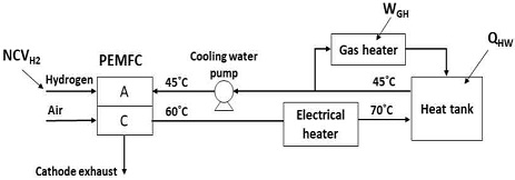
Fig. 2 describes reference cogeneration system using heater to heat up cooling water exited from PEMFC before supplying to heat tank for thermal storage.
PEMFC with efficiency of 50% uses hydrogen to generate electricity while 45℃ water will be pumped into PEMFC as cooling water. Going through a 65℃ PEMFC, cooling water is heated up to 60℃. Then, a heater is employed to heat up cooling water once again to 70℃ to match temperature requirement at heat tank. Finally, hot water realizes heat for thermal storage, becoming 45℃ water, then being recirculated as cooling water. However, the electricity produced is not enough to heat up cooling water to match 20 kW thermal demand; consequently, a gas heater with efficiency of 90% is employed to cover remaining demand.
Other assumptions and specifications used for the PEMFC based cogeneration system are given in Table 1.
2.2 Proposed layouts
As discussed in section I, heat pump provides a more efficient heating up method than that of heater. However, COPs of heat pump depend dominantly on refrigerant and operating pressures.
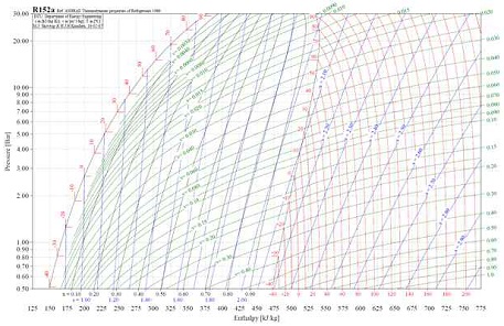
Because the heat tank requires input temperature of 70℃, the refrigerant is required to operate at temperature higher than 70℃, then condenses at 70℃ at appropriate pressure. Among common refrigerants, R134a, R22, and R152a become three most promising candidates. Besides, according reference, R152a has superior thermodynamic characteristics to R134a, leading to 20% higher energy efficiency in the same refrigeration system9). Fig. 3 shows the p-h diagram of R152a. In addition, to condense at 70℃, R152a required lowest compressed pressure as shown in Table 2 where R152a has least environmental impact among three refrigerants. By considering all mentioned factors, R152a is selected as refrigerant for heat pump layouts in this study.
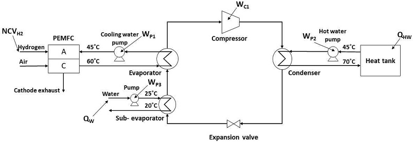
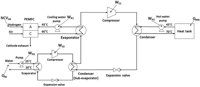
As shown in Fig. 4, the hot water exited from PEMFC is supplied to evaporator where refrigerant evaporates completely by receiving transferred heat. Then, gaseous refrigerant is compressed and pressurized to 20 bars, coming to condenser to heat up water from 45 to 70℃ for thermal storage at heat tank. After releasing heat, gaseous refrigerant condenses, then becomes liquid refrigerant after exiting condenser. The liquid refrigerant then goes to the expansion valve where it expands, losing pressure and heat. The cold liquid refrigerant exiting from expansion valve absorbs heat at sub-evaporator for partial evaporation before coming to evaporator for complete vaporization. The heat supplied to heat tank comprises absorbed heat at sub-evaporator and evaporator beside work done by compressor. Consequently, the rate between useful thermal energy and compression work increases significantly.
As shown in Fig. 5, the second proposal is a cascade heat pump in which the sub-evaporator in the previous layout is repalced by a sub-heat pump loop in order to minimize compression work, leading to a higher total system efficiency. Condensing temperature in the sub-heat pump loop is set at 45℃.
2.3 System thermal efficiency and COP
To measure the efficiency of a cogeneration system, the system thermal efficiency is defined and used. It is the percent of the both electricity and useful thermal energy to input energy which is described by Eq. 2.
| (2) |
- where:
- QHW : total heat transferred to heat tank
- En : remaining amount of electricity after being consumed by devices in the system
- NCVH2 : net calorific value of hydrogen input
- QW : heat of water transferred at sub-evaporator
- WGH : work done by gas heater
However, normally for system including a heat pump loop the heat input is not considered because it comes from ambient air or ambient water. Only the pumping or blowing work are taken into account. In scope of this paper, system COP is introduced and defined as percent of the both electricity and useful thermal energy to input fuel energy, described by Eq. 3.
| (3) |
Besides, COP of heat pump itself is calculated to compare performance of heat pumps loop, described by Eq. 4.
| (4) |
- where:
- ∑WC : total work done by compressors
- ∑WP : total work done by pumps
3. Results and discussion
Table 3 shows the performance results of the reference and two proposal layouts. All of layout match demands of 5 kW for electricity and 20 kW for thermal energy. There is not much difference in thermal efficiency among all cases. In detail, the proposal with cascade heat pump has highest thermal efficiency of 0.89 while the reference layout gets lowest number, 0.87. However, in fact, the system COP are more meaning full in this comparison because the heat from ambient water can be neglected. In this point of view, both proposals with heat pump loop shows superior system COPs to that of layout with heaters. From 0.87 at reference, the system COP sharply increases to 1.26 and 1.29 at proposal one and proposal two, respectively. Thank to heat pump loop, a significant amount of heat from ambient water can be absorbed to be refrigerant thermal heat, then, released to hot water with a negligible pumping work.
In both two proposed layouts, an amount of 20℃ water is generated as by-product from ambient water (25℃). In the case this water is utilized, the cogeneration system can become tri-generation system while the system COPs are even improved to 1.70 and 1.74 for proposal one and proposal two, respectively. Thank to heat pump configurations which both have COP greater than four, a significant amount of heat from ambient water can be absorbed to be refrigerant thermal heat, then, released to hot water with a negligible pumping work.
Between two proposed layouts, the system with cascaded heat pump always show better result but not much superior while it is more complicated than the system with normal heat pump. A further economic analysis should be carried out to have a more comprehensive comparison between two proposals.
4. Conclusions
This study has proposed and analyzed two cogeneration systems of PEMFC coupled with heat pump loop in a comparison with a reference layout using PEMFC and heaters.
The first conclusion is that the heat pump layouts improve system COP noticeably, from 0.87 to 1.26 and 1.29. Especially, the system with cascade heat pump show the best performance at all comparisons.
Secondly, if cooling water can be considered as a by-product, the system COPs of two proposals are even significant improved to 1.70 and 1.74, respectively. In that case, tri-generation systems should be introduced and deeply developed.
Finally, a further economic analysis should be carried out to have a more comprehensive comparison between two proposals and reference configuration.
Acknowledgments
This work was carried out with the support of “Cooperative research program for agriculture science and technology development (Project No. PJ016288, Development of horticultural energy model based on hydrogen fuel cell tri-generation system)” rural development administration, Republic of Korea.
References
-
J. Larminie and A. Dicks, “Fuel cell systems explained, second edition”, John Wiley & Sons, Ltd., 2003.
[https://doi.org/10.1002/9781118878330]

-
J. C. Lin, “Development of a PEMFC-based heat and power cogeneration system”, International Journal of Green Energy, Vol. 15, No. 9, 2018, pp. 517-531.
[https://doi.org/10.1080/15435075.2018.1489252]

-
Y. Wang, H. Yuan, A. Martinez, P. Hong, H. Xu, and F. R. Bockmiller, “Polymer electrolyte membrane fuel cell and hydrogen station networks for automobiles: status, technology, and perspectives”, Advances in Applied Energy, Vol. 2, 2021, pp. 100011.
[https://doi.org/10.1016/j.adapen.2021.100011]

-
L. Eudy, K. Chandler, and C. Gikakis, “Fuel cell buses in U.S. transit fleets: summary of experiences and current status”, National Renewable Energy Laboratory, 2007, Retrieved from https://www.nrel.gov/docs/fy07osti/41967.pdf, .
[https://doi.org/10.2172/915290]

-
C. H. Choi, S. J. Yu, I. S. Han, B. K. Kho, D. G. Kang, H. Y. Lee, M. S. Seo, J. W. Kong, G. Y. Kim, J. W. Ahn, S. K. Park, D. W. Jang, J. H. Lee, and M. J. Kim, “Development and demonstration of PEM fuel-cell-battery hybrid system for propulsion of tourist boat”, International Journal of Hydrogen Energy, Vol. 41, No. 5, 2016, pp. 3591-3599.
[https://doi.org/10.1016/j.ijhydene.2015.12.186]

- Y. Yamada and K. Nishizaki. “Next generation model of the world's first residential PEMFC cogeneration system goes on sale”, 24th World Gas Conference, 2009, pp.1-7, Retrieved from http://members.igu.org/html/wgc2009/papers/docs/wgcFinal00432.pdf, .
- J. Mitchell and J. E. Braun, “Principles of heating, ventilation, and air conditioning in buildings”, Wiley, 2012, Retrieved from https://www.wiley.com/en-us/Principles+of+Heating%2C+Ventilation%2C+and+Air+Conditioning+in+Buildings-p-9780470624579, .
-
I. Dincer and M.A. Rosen, “Exergy analyses of refrigeration and heat pump systems”, Edition, 2021, pp. 125-141.
[https://doi.org/10.1016/B978-0-12-824372-5.00007-5]

- “Unknown and surprising R152a”, INTARCON, Retrieved from https://www.intarcon.com/en/refrigerante-r152a/, .
