Type 2 고압용기를 위한 금속선재의 Hoop Wrap에 관한 이론 연구
2020 The Korean Hydrogen and New Energy Society. All rights reserved.
Abstract
Recently, Type 2 high-pressure hydrogen storage tank is studied due to fast defect detection, easy manufacturing, and cost efficiency. Moreover, the dry winding a high-strength metal wire will make increased economic efficiency compare with the wet winding method and the carbon/glass fiber winding method. In this study, a theoretical study on the dry winding of a Type 2 high pressure hydrogen tank using a metal wire was done, and the equations of the total stress on the aligned and the staggered winding for the hoop winding were derived, and the following results were obtained by using these equations. As the diameter of the metal wire, the number of winding layers, and the outer diameter of the liner increase, the maximum stress decreases, but the difference between the maximum stress occurring in the aligned winding and the staggered winding increases. As the pressure increases, the thickness of the winding layer increases, but as the strength of the metal wire increases, the thickness of the winding layer decreases. In addition, regardless of the strength of the metal wire, the thickness of the winding layer of the staggered winding was about 13.4% thinner than that of the aligned winding.
Keywords:
Type 2 high pressure tank, Hoop wrap, Metal wire, Dry winding, Aligned, Staggered, Winding layers키워드:
Type 2 고압용기, 후프 권선, 금속선재, 건식 권선, 정렬, 엇갈림, 권선층수1. 서 론
1880년 연철재 압력용기에 수소를 12 MPa의 압력으로 저장하는 기술이 고압수소 저장탱크의 기원으로 알려져있다1). 현재 수소를 저장하는 일반적인 방법은 고압용기에 20 MPa의 수소를 저장하는 방법이며2,3), 고압용기 재료로는 인장강도 460 MPa의 스테인레스강을 활용하고 있다. 그러나 수소의 저장 압력이 증가함에 따라 고압용기의 두께가 증가하므로, 제작 및 용기 결함 검출의 어려움 등의 많은 단점을 가지고 있다. 이와 같은 단점을 보완하기 위해 높은 압력을 견딜 수 있도록 고압수소 저장용기의 두께를 줄이는 다양한 연구개발이 진행되고 있다4).
스테인레스강의 단일 재료 고압수소 저장용기보다 두께는 얇고, 더 높은 압력에 견딜 수 있도록 2종 이상의 소재를 사용하여 만든 용기구조로 다음과 같이 4가지 Type의 고압저장용기로 개발되어 구조와 재료에 따라 분류하고 있다.
Type 1: 단일 소재의 금속압력용기로 20-30 MPa의 압력으로 저장되며, 주로 산업용 수소저장용기로 사용된다. 용기 중량 대비에 1 wt%의 수소만 저장이 가능하기에 저장효율이 낮다5).
Type 2: 금속용기의 길이 방향 외측에만 유리섬유기반 복합재를 hoop wrap 권선 접착한 용기로 Type 1 금속용기보다 제작비용이 50% 더 비싸지만, 용기 무게는 30-40% 가볍다. 다른 Type의 고압용기와 비교하여 가장 높은 압력의 저장용기 개발이 가능한 방법으로 알려져 있다6).
Type 3: 탄소/유리 섬유기반 복합재를 이용하여 금속라이너의 모든 표면을 full wrap 권선 접착한 용기로 용기 무게는 Type 2의 절반이지만, 제작비가 2배 정도 비싸다. 최근 저장압력이 35 MPa과 70 MPa급 용기로 제작되어 수소연료전지 자동차용으로 사용된다4). 작동 압력이 45 MPa일 때 신뢰성은 입증되었지만 75 MPa에서의 수명시험이 문제가 되고 있다7).
Type 4: 경량 고강도 폴리머 라이너에 탄소섬유기반 복합재를 full wrap 권선 접착한 압력용기로, 용기의 무게가 가장 가볍지만 제작 가격은 가장 비싸며, 100 MPa의 압력까지 견딜 수 있다6).
수소연료전지 자동차의 상용화를 위한 활발한 연구개발로 고압저장이 가능한 경량 Type 3, Type 4 수소저장용기 기술개발과 상용화가 크게 진전되어 있다. 그러나 수소연료전지 자동차의 상용화에 있어 가장 어려운 요인으로 부족한 수소충전소로 인한 수소 충전의 어려움이며, 수소충전소의 보급이 더딘 가장 근본적인 원인은 수소충전시설의 설치비용이 높다는 것이다.
수소충전소용 정치형 압력용기는 자동차용 압력용기와 같은 이동형 압력용기보다 무게와 부피에 대한 제약이 심하지 않다. 따라서 상대적으로 무겁지만 저장압력이 높고 가격이 저렴한 Type 2 고압용기가 다른 Type의 저장용기보다 수소충전소용으로 적합하다.
권선 공법인 습식 권선과 건식 권선 공법 비교하였을 때 건식 권선 방법이 더 저렴한 것으로 알려져 있으며8) 레진을 이용하여 유리/탄소섬유를 권선 접착하는 습식 권선(wet winding)으로 제작되는 Type 2-4 압력용기9,10)의 제작비용을 낮출 수 있는 방법으로 건식 권선(dry winding) 공법이 관심을 받고 있다. 건식 권선 공법으로 수소저장용기를 제작 시, 고강도 금속선재를 이용한 금속선재 권선(metal wire winding) 공법이 탄소섬유와 유리섬유를 이용한 공법보다 재료비가 낮아 더 저렴하게 제작할 수 있다.
최근 용이한 불량 검출과 저가형 Type 2의 권선재와 권선방법을 저렴하고 불량 검출이 용이한 금속선재를 건식 권선방법으로 제작하는 저결함과 저가형 Type 2 고압수소 저장용기의 연구개발8,11)이 진행되고 있다. 건식 권선방법으로 설계와 제작에 필요한 라이너와 금속선재의 다양한 조건에 관한 연구12-18)도 진행되고 있으나, 금속선재의 건식 권선 방법에 관한 이론해 유도와 같은 이론적인 연구는 전무한 실정이다. 본 연구에서는 Type 2 고압 수소저장용기 설계에 필요한 금속선재의 건식 hoop wrap 권선방법에 대한 이론적인 연구를 수행하였다.
2. 건식 Hoop 권선된 금속선재의 응력에 관한 유도
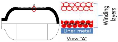
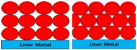
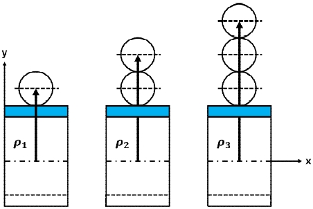
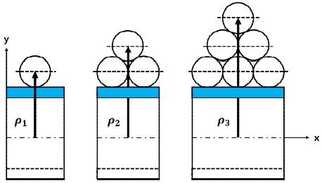
Fig. 1에 나타낸 구조와 같이 Type 2 수소저장용기를 건식 공법을 이용하여 제작할 경우 고압수소의 기밀용 요소인 금속 라이너 위에 Fig. 2와 같이 금속선재는 정렬(aligned) 또는 엇갈림(staggered)의 두 가지 권선방법으로 적층된다.
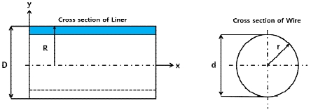
Fig. 3과 같은 라이너와 권선용 금속선재 모델을 이용하여 금속선재에 발생하는 응력에 관한 이론해석을 수행하였다.
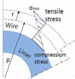
Fig. 4와 같이 외경의 반지름이 R인 라이너 위에 반지름이 r인 선재를 권선할 경우 선재에서 발생하는 최대응력(σmax)은 식 (1)과 같다.
| (1) |
여기서 E는 금속선재의 탄성계수(modulus of elasticity)이며 라이너 위에 적층되는 권선재의 곡률반경은 이 되며, y = r에서 최대응력과 변형이 발생한다.
고압 용기의 경우 압력이 증가할수록 라이너 위에 권선하여 적층되는 선재의 권선층수가 증가하므로 수소저장압력에 적합한 정렬권선과 엇갈림권선에 대한 권선층수(winding layers)의 결정이 필요하다.
먼저 정렬권선의 경우 Fig. 5에서 볼 수 있는 것과 같이 권선층수가 증가할수록 식 (2)와 같이 곡률 반경이 증가하기 때문에 권선된 각각의 선재들에 대한 최대응력은 다음과 같다.
| (1‘) |
| (2) |
따라서 정렬권선에 대한 식 (1)은 권선층수가 증가할수록 최외각에 권선된 금속선재에 작용하는 최대응력은 식 (3)과 같다.
| (3) |
고압용기의 라이너 외부에 권선되는 모든 금속선재들에 작용하는 총응력(σtotal)은 식 (3)의 각각의 권선된 층수들이 받는 최대응력의 수열의 합으로 유도할 수 있으며 식 (4)와 같다.
| (4) |
여기서 n(권선층수)=1, 2, 3, ···이다.
또한 엇갈림권선의 경우 Fig. 6과 같이 권선 횟수가 증가할수록 식 (5)와 같이 곡률 반경이 증가한다.
| (5) |
따라서 엇갈림권선에 대한 최대응력은 식 (1)에서 권선층수가 증가할수록 권선된 각각의 선재의 경우 권선되는 선재의 최대응력은 식 (6)과 같이 변한다.
| (6) |
고압용기에서 권선된 금속선재들이 받는 최대응력의 합인 총응력(σtotal)은 식 (6)의 수열의 합으로 계산되며 식 (7)과 같다.
| (7) |
여기서 n(권선층수)=1, 2, 3,···이며, θ=60°이다.
3. 이론해석 결과
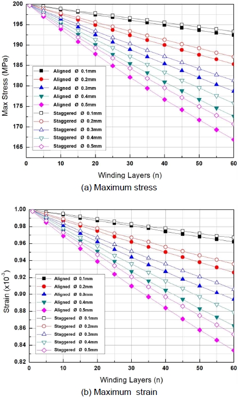
Fig. 7은 외경이 300 mm인 라이너에 직경이 0.1 mm, 0.2 mm, 0.3 mm, 0.4 mm, 0.5 mm인 금속선재를 정렬 및 엇갈림권선방법을 이용하여 1-60회까지 권선할 경우에 금속선재에 발생하는 최대 응력과 변형을 보여주고 있다.
Maximum stress and strain on the wire diameter and the winding method and the number of winding layers when winding on ϕ300 mm liner
1층의 정렬과 엇갈림권선에서 금속선재의 직경에 따른 차이가 약 200 MPa (1.0×10⁻³)로 선재직경에의 변화에 따른 차이가 매우 작은 최대응력(최대변형률)은 60층의 정렬과 엇갈림권선에서는 금속선재의 직경이 0.1 mm인 경우 192.4 MPa (0.962×10⁻³)과 193.3 MPa (0.967×10⁻³)로 약 3.8%와 3.3% 정도 선형적인 감소를 하였다. 금속선재의 직경이 0.5 mm인 경우 166.9 MPa (0.834×10⁻³)과 170.7 MPa (0.853×10⁻³) 정도로 약 16.4%와 14.5% 정도까지 선형적으로 감소하였으며, 금속선재의 직경의 크기와 권선층수가 증가할수록 최대 응력과 변형은 감소하는 것을 알 수 있다. 그러나 권선층수 60회의 정렬과 엇갈림권선에서 0.1 mm와 0.2 mm와의 최대응력(최대변형률) 차이는 7.1 MPa (0.036×10⁻³)과 6.2 MPa (0.031×10⁻³)이며, 0.4 mm와 0.5 mm와의 최대응력(최대변형률) 차이는 5.7 MPa (0.029×10⁻³)과 5.1 MPa (0.026×10⁻³)로 금속선재의 직경이 증가할수록 최대응력(최대변형률)의 감소폭은 조금씩 줄어드는 것을 알 수 있다. 아울러 권선층수 60회시에 직경 0.1 mm와 0.5 mm의 금속선재를 이용한 정렬과 엇갈림권선 시 금속선재에서 발생하는 최대응력(최대변형률)의 변화는 0.9 MPa (0.005×10⁻³)와 3.8 MPa (0.019×10⁻³)로 그 차이는 증가하여, 권선층수가 증가 및 금속선재 직경의 증가와 함께 정렬과 엇갈림권선에서 발생하는 최대응력(최대변형률)의 차이가 증가하는 것을 알 수 있다.
Fig. 8은 직경이 0.3 mm인 금속선재로 권선할 경우 200 mm, 300 mm, 400 mm의 라이너 외경과 정렬 및 엇갈림권선방법을 이용하여 1-60층까지 권선할 시 금속선재에 발생하는 최대 응력과 변형을 나타낸 것이다.
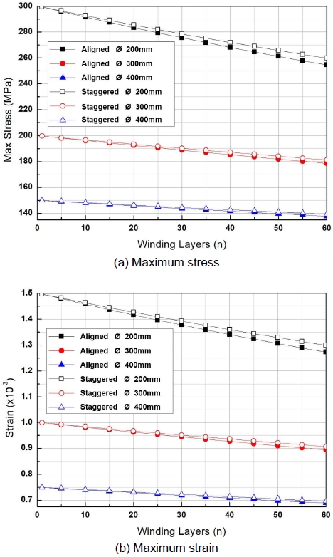
Maximum stress and strain on the outer diameter of the liner and the winding method and the number of winding layers when winding with ϕ0.3 mm metal wire
외경이 200 mm와 400 mm인 라이너 위에, 1회 권선할 경우 금속선재에서 발생하는 최대응력(최대변형률)은 각각 299.6 MPa (1.498×10⁻³)과 149.9 MPa (0.749×10⁻³)로 라이너 직경비인 2배에 반비례하여 약 50.0%로 감소하였으며, 정렬과 엇갈림권선에서 최대응력(최대변형률)은 같은 것을 알 수 있다. 그러나 60회의 정렬권선을 할 경우 금속선재에서 발생하는 최대응력(최대변형률)은 각각 257.2 MPa (1.286×10⁻³)과 138.5 MPa (0.693×10⁻³)로 약 46.2% 차이로 그 차이가 서서히 감소하는 것을 알 수 있으며, 정렬과 엇갈림권선에서 최대응력(최대변형률)도 매우 작게 차이가 발생하여 라이너 외경이 200 mm인 경우 5.2 MPa (0.026×10⁻³)로, 라이너 외경이 400 mm인 경우 1.5 MPa (0.007×10⁻³)로 라이너 외경이 작을수록 정렬과 엇갈림권선방법에 따른 최대응력(최대변형률)의 차이가 조금씩 증가하는 것을 알 수 있다.
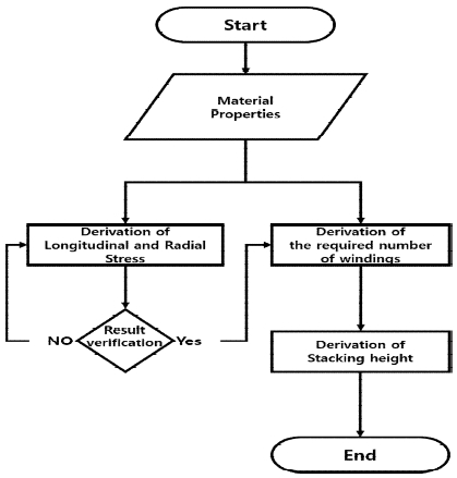
건식 Type 2 고압 수소저장용기의 라이너 위에 hoop 권선되는 정렬과 엇갈림권선방법에 대한 권선층수와 권선층의 두께는 2절에서 유도한 식 (4)와 식 (7)의 이론식 등을 바탕으로 Fig. 9와 같은 계산절차에 의해 구할 수 있다.
Table 1은 용기내부압력이 80 MPa, 안전계수가 3, 라이너 외경과 두께가 각각 300 mm와 30 mm, 라이너의 탄성계수가 200 GPa 그리고 권선되는 금속선재의 직경이 0.3 mm인 경우에 금속선재의 강도가 200 MPa에서 500 MPa까지 50 MPa씩 증가할 경우에 권선층수와 정렬 및 엇갈림권선층의 두께를 계산한 결과이다.

The relation between the strength of ϕ0.3 mm metal wire and the number of winding layers and the thickness of the winding layer when the hydrogen storage pressure is 80 MPa (safety factor 3, liner outer diameter 300 mm, liner thickness 30 mm, liner elastic modulus 200 GPa)
금속선재의 강도가 200 MPa에서 400 MPa과 500 MPa로 2배와 2.5배로 증가할 경우 선재의 권선층수는 484에서 179와 118로 각각 63.0%와 75.6%로 크게 줄어드는 것을 알 수 있다. 아울러 권선층의 두께는 직경이 0.3 mm인 금속선재의 강도가 200 MPa에서 400 MPa과 500 MPa로 증가할 경우 정렬권선의 권선층의 두께는 145.0 mm에서 53.3 mm와 35.0 mm로, 엇갈림권선의 권선층의 두께는 125.6 mm에서 46.2 mm와 35.0 mm로, 2가지 권선방법은 권선층수와 같은 비율로 크게 줄어드는 것을 알 수 있다. 또한 정렬과 엇갈림권선의 권선층의 두께는 엇갈림권선층의 두께가 정렬의 경우보다 약 13.4%로 금속선재의 강도와 무관하게 일정하게 얇았으며, 엇갈림권선이 정렬권선보다 체적 용기의 체적효율이 높다는 것을 알 수 있다.
Fig. 10은 안전계수가 3, 라이너의 외경과 두께가 각각 300 mm와 30 mm, 라이너의 탄성계수가 200 GPa 그리고 권선되는 금속선재의 직경이 0.3 mm인 경우에 금속선재의 강도가 200 MPa에서 500 MPa까지 50 MPa씩 증가할 경우와 수소저장압력이 70 MPa, 80 MPa, 90 MPa인 경우 및 정렬 및 엇갈림권선 방법에 관한 권선층의 두께를 계산한 결과이다.
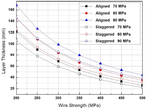
The relation between thickness of the winding layer and the strength of ϕ0.3 mm metal wire and the winding method and the storage pressure (safety factor 3, liner outer diameter 300 mm, liner thickness 30 mm, liner elastic modulus 200 GPa)
강도가 200 MPa인 금속선재로 수소저장압력이 70 MPa, 80 MPa, 90 MPa인 용기를 정렬 권선하여 제작할 경우, 권선층의 두께는 각각 122.08 mm, 145.00 mm, 167.92 mm로 수소저장압력이 10 MPa씩 증가함에 따라 권선층의 두께가 22.92 mm 증가하였다. 그러나 강도가 500 MPa인 금속선재로 수소저장압력이 70 MPa, 80 MPa, 90 MPa인 용기를 정렬권선하여 제작할 경우 권선층의 두께는 각각 25.82 mm, 34.99 mm, 44.16 mm로 수소저장압력이 10 MPa씩 증가함에 따라 권선층의 두께가 9.17 mm 증가하였다. 또한 강도가 200 MPa인 금속선재로 수소저장압력이 70 MPa, 80 MPa, 90 MPa인 용기를 정렬권선과 엇갈림권선으로 제작할 경우 두께의 차이는 각각 16.33 mm, 19.41 mm, 22.48 mm로 수소저장압력이 10 MPa씩 증가함에 따라 권선층의 두께가 약 3.08 mm 증가하였으며, 강도가 500 MPa인 금속선재로 제작할 경우 정렬권선과 엇갈림권선에 의한 두께의 차이는 각각 3.34 mm, 4.67 mm, 5.90 mm로 수소저장압력이 10 MPa씩 증가함에 따라 권선층의 두께가 약 1.28 mm 증가하였으나, 두 권선방법에 의한 권선층의 두께차이는 금속선재의 강도가 증가함에 따라 감소한다. 아울러 금속선재의 강도와 무관하게 엇갈림권선의 권선층의 두께가 정렬권선보다 약 13.4%로 얇았으며, 용기의 체적효율이 좋다는 것을 알 수 있다.
4. 결 론
본 연구에서는 비접착식인 건식 hoop wrap 방식 Type 2 고압 수소저장용기 설계에 필요한 금속선재 권선방법에 대한 이론적인 연구를 수행하였으며, 고체의 굽힘에서 발생하는 최대응력 식을 기초로 정렬권선과 엇갈림권선으로 hoop 권선 시 권선된 선재들의 총응력을 식 (4)와 식 (7)과 같이 유도하였으며, 다음과 같은 결과를 얻었다.
1) 금속선재의 직경의 크기와 권선층수가 증가할수록 최대응력(최대변형률)은 감소한다. 그러나 금속선재의 직경이 증가할수록 최대응력(최대변형률)의 감소량은 조금씩 줄어든다.
2) 권선층수가 증가 및 금속선재 직경의 증가와 함께 정렬과 엇갈림권선에서 발생하는 최대응력(최대변형률)의 차이가 증가한다.
3) 라이너 외경이 증가함에 따라서 1회의 권선에서 최대응력(최대변형률)은 감소하였으나, 권선층수가 증가할수록 감소율은 작아진다.
4) 라이너 외경의 증가에 따른 1회의 권선배열과 정렬과 엇갈림권선에서의 최대응력(최대변형률)은 같았다. 그러나 권선층수가 증가할수록 엇갈림권선이 정렬보다 최대응력(최대변형률)이 미소하게 작았으며, 라이너 외경이 증가할수록 그 차이는 더 줄어든다.
5) 수소저장압력이 증가할수록 권선층의 두께는 증가하나, 금속선재의 강도가 증가할수록 권선층의 두께 차이는 줄어든다.
6) 정렬권선과 엇갈림권선에 의한 권선층의 두께차이는 금속선재의 강도가 증가함에 감소하지만, 금속선재의 강도와 무관하게 엇갈림권선의 권선층의 두께가 정렬권선의 경우보다 약 13.4%로 얇으며, 용기의 체적효율은 증가한다.
Acknowledgments
본 연구는 금오공과대학교 학술연구비의 지원을 받아 수행한 연구 과제(2017-104-092)입니다.
References
-
Barthelemy H, Weber M, and Barbier F. “Hydrogen storage: recent improvements and industrial perspectives”, Int. J. Hydrogen Energy, Vol. 42, No. 11, 2017, pp. 7254–7262.
[https://doi.org/10.1016/j.ijhydene.2016.03.178]

-
J. Ogden, A. M. Jaffe, D. Scheitrum, Z. McDonald, and M. Miller, “Natural gas as a bridge to hydrogen transportation fuel: insights from the literature”, Energy Policy, Vol. 115, 2018, pp. 317–329.
[https://doi.org/10.1016/j.enpol.2017.12.049]

-
E. Wolf, “Chapter 9 - large-scale hydrogen energy storage”, Electrochemical Energy Storage for Renewable Sources and Grid Balancing, 2015, pp. 129-142.
[https://doi.org/10.1016/B978-0-444-62616-5.00009-7]

-
R. Krishna, E. Titus, M. Salimian, O. Okhay, S. Rajendran, A. Rajkumar, J. M. G. Sousa, A. L. C. Ferreira, J. C. Gil, and J. Gracio, “Hydrogen storage for energy application”. Hydrogen Storage, 2012, pp. 243-266.
[https://doi.org/10.5772/51238]

- T. Lipman, “An overview of hydrogen production and storage systems with renewable hydrogen case studies”, Conducted under US DOE Grant: DE-FC3608GO18111 A000, Office of Energy Efficiency and Renewable Energy Fuel Cell Technologies Program, 2011. Retrieved from https://www.cesa.org/assets/2011-Files/Hydrogen-and-Fuel-Cells/CESA-Lipman-H2-prod-storage-050311.pdf, .
-
R. Moradi and K. M. Groth “Hydrogen storage and delivery: review of the state of the art technologies and risk and reliability analysis”, Int. J. Hydrogen Energy, Vol. 44, No. 23, 2019, pp. 12254-12269.
[https://doi.org/10.1016/j.ijhydene.2019.03.041]

-
A. Zuettel, “Materials for hydrogen storage”, Materials Today, Vol. 6, No. 9, 2003, pp. 24–33.
[https://doi.org/10.1016/S1369-7021(03)00922-2]

- F. W. DuVall, “Cost comparisons of wet filament winding versus prepreg filament winding for type II and type IV cng cylinders”, ICCM, 12th, International Conference on Composite Materials, Paris, 1999, pp. 686. Retrieved from https://www.iccm-central.org/Proceedings/ICCM12proceedings/site/papers/pap187.pdf, .
- T. H. Lim, J. I. Byun, M. S. Cho, and H. S. Kim, “Design and structural analysis of type 4 composite pressure vessel fitted in spare tire well”, Trans. of the Korean Hydrogen and New Energy Society, Vol. 29, No. 6, 2018, pp. 570-577.
- H. K. Kang, J. S. Park, C. U. Kim, D. H. Kang, C. S. Hong, and C. G. Kim, “Behavior analysis and strain measurement of filament wound composite tank - part Ⅱ. strain measurement using fiber optic sensors”, Journal of the Korean Society for Aeronautical & Space Sciences, Vol. 29, No. 8, 2001, pp. 96-102. Retrieved from http://www.dbpia.co.kr/journal/articleDetail?nodeId=NODE01099205, .
-
R. Stewart, “Filament winding spins light, strong composite structures with precision”, Reinforced Plastics, Vol. 53, No. 5, pp.34-39.
[https://doi.org/10.1016/S0034-3617(09)70223-1]

-
S. Koussios and O. K. Bergsma, “Friction experiments for filament winding applications”, Journal of Thermoplastic Composite Materials, Vol. 19, No. 1, 2006, pp. 5-34.
[https://doi.org/10.1177/0892705706049561]

-
J. M. Alegre, P. Bravo, M. Preciado, and M. Solaguren-Beascoa, “Simulation procedure of high pressure vessels using the wire winding technique”, Engineering Failure Analysis, Vol. 17, No. 1, 2010, pp. 61-69.
[https://doi.org/10.1016/j.engfailanal.2008.11.004]

- B. G. Park, “Development of 100L-700MPa high pressure vessel design technique using finite element analysis”, Korean Society for Precision Engineering Academic Conference, 2019, pp. 72. Retrieved from http://www.dbpia.co.kr/journal/articleDetail?nodeId=NODE08742208, .
- J. B. Park and J. H. Noh, “A study on the wire winding technique of ultra high pressure vessel for the improvement of physical properties”, Korean Society for Precision Engineering Academic Conference, 2017, pp. 651. Retrieved from http://www.dbpia.co.kr/journal/articleDetail?nodeId=NODE07205777, .
-
S. Kim and C. Lee, “Study on the radial stress considering mechanical characteristics of substrate in wound rolls”, Journal of the Korean Society for Precision Engineering, Vol. 33, No. 2, 2016, pp. 115-119.
[https://doi.org/10.7736/KSPE.2015.33.2.115]

- B. G. Park and H. J. Lee, “FE analysis of high pressure vessels using the wire-winding technique”, The Korean Society of Mechanical Engineers Academic Conference, 2018, pp. 2630-2633. Retrieved from http://www.dbpia.co.kr/journal/articleDetail?nodeId=NODE07607815, .
- J. M. Han, S. K. Choi, S. H. Lee, K. C. Cho, C. M. Hwang, and Y. G. Jung, “A study on the metal wire for hoop wrapping of type 2 high pressure tank”, Trans. of Korean Hydrogen and New Energy Society, Vol. 30, No. 4, 2019, pp. 338-346.
