이동식수소스테이션 정량적 위험성평가에 관한 연구
2020 The Korean Hydrogen and New Energy Society. All rights reserved.
Abstract
In July and October of this year, the government announced the 'Green new deal plan within the Korean new deal policy' and 'Strategies for proliferation of future vehicles and market preoccupation'. And, in response to changes in the global climate agreement, it has decided to expand green mobility such as electric vehicles and hydrogen electric vehicles with the aim of a “net-zero” society. Accordingly, the goal is to build 310 hydrogen refueling stations along with the supply of 60,000 hydrogen vehicles in 2022, and the hydrogen infrastructure is being expanded. however, it is difficult to secure hydrogen infrastructure due to expensive construction costs and difficulty the selection of a site. In Korea, it is possible to build a mobile hydrogen station according to the safety standards covering special case of the Ministry of Industry. Since the mobile hydrogen station can be charged while moving between authorized place, it has the advantage of being able to meet a large number of demands with only one hydrogen refueling station, so it is proposed as a model suitable for the early market of hydrogen infrastructure. This study demonstrates the establishment of a hydrogen refueling station by deriving a virtual accident scenario for leakage and catastrupture for each facility for the risk factors in a mobile hydrogen station, and performing a quantitative risk assessment through the derived scenario. Through the virtual accident scenario, direction of demonstration and implications for the construction of a mobile hydrogen refueling station were derived.
Keywords:
Mobile hydrogen refueling station, Fuel cell electric vehicle (FCEV), Risk assessment, Safety standards, Individual/societal risk키워드:
이동식수소스테이션, 수소전기차, 위험성평가, 안전기준, 개인적/사회적 위험도1. 서 론
정부는 2020년 7월 “한국판 뉴딜 내 그린뉴딜 계획”, 2020년 10월 “미래자동차 확산 및 시장선점 전략”을 발표하며 글로벌 기후협약변화에 대응하여 “탄소중립(net-zero)”사회를 지향점으로 전기차, 수소전기차 등 그린모빌리티의 확대를 추진하기로 하였다1). 이에 따라 2022년까지 수소자동차 6만 대 보급과 함께 수소충전소 310개 구축을 목표로 수소충전인프라 확대를 추진 중에 있다. 그러나 2020년 10월 기준 구축된 수소충전소는 51개소로 목표 달성을 위해서는 이를 더욱 가속화 할 필요가 있으나, 고가의 구축비용 및 부지 확보의 어려움으로 인해 수소충전인프라 확보에 어려움이 있는 실정이다2).
국내에서는 산업부 특례기준(산업부 고시 제2018-179호, 2018년 10월 1일, ‘융·복합, 패키지형 및 이동식 자동차충전소 시설기준 등에 관한 특례기준’)에 의해 이동식수소스테이션 구축이 가능하다3). 이동식수소스테이션은 수소를 연료로 사용하는 자동차에 수소를 충전하기 위하여 필요한 설비(필요한 경우 충전설비는 제외할 수 있다)가 차량에 장착되어 있어 이동이 가능한 것으로서 처리능력 30 m3 이상인 것(압축기 등 가압장치 없이 자압에 의해 충전하는 설비는 제외한다)으로 정의되어 있다. 이동식수소스테이션은 허가받은 장소 간 이동하며 충전이 가능하고, 하나의 충전소로 다수의 수요를 충족시킬 수 있는 장점으로 수소인프라 보급 초기시장에 적합한 모델로 제시되고 있다4).
이동식수소스테이션은 처리설비(압축기), 압축가스설비(저장용기), 충전설비(디스펜서) 등의 핵심설비가 충전소 차량에 탑재된 상태로 충전사이트 간 이동하는 것으로서, 70 MPa의 초고압 수소가스가 밀폐공간에서 누출 발생 시 대형 화재 및 폭발사고로 이어 질 수 있어 안전성 확보를 위한 위험요소 분석이 필요하다.
본 연구에서는 향후 실증사이트로 구축될 예정인 충청북도 충주 부지의 이동식수소스테이션의 위험요인에 대해 설비별 누출 및 파열로 인한 사고 시나리오를 도출하고, 도출된 시나리오를 통해 정량적 위험성평가(quantitative risk assessment, QRA)를 수행함으로서 충전소 구축에 대한 실증방향과 시사점을 도출하였다.
2. 이동식수소스테이션 개요
2.1. 이동식수소스테이션 기초데이터
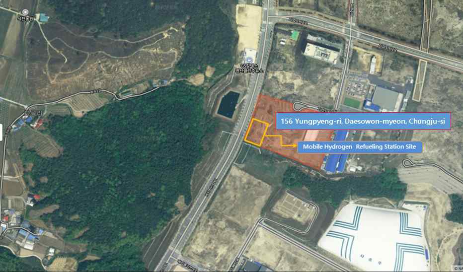
본 연구는 현재 국내에서 이동식수소스테이션 1호로 구축될 예정인 “충주 이동식수소스테이션”을 대상으로 하였다. 충전소 실증 부지 주변은 Fig. 1과 같이 민간 거주시설이 없고 인구 밀도가 낮은 지역으로, 산업시설과 약 150 m, 교회와 약 120 m, 셀프주유소와 약 140 m, 2021년 입주 예정인 오피스텔과 약 250 m가 떨어져 위치하고 있으며, 왕복 6차선 도로가 인접한 부지에 이동식수소스테이션이 구축될 예정이다.
2.2. 실증용 이동식수소스테이션 설비
일반적인 고정식 수소충전소(저장식)의 핵심설비는 저장설비, 압축기, 저장용기, 디스펜서로 구성할 수 있다5). 튜브트레일러를 통해 약 20 MPa의 수소를 이송 받아, 압축기를 통해 약 90 MPa의 고압으로 압축 한 후 압축가스설비에 저장하고, 디스펜서를 통해 수소자동차에 약 35 MPa 혹은 70 MPa의 충전압력으로 공급한다.
이동식수소스테이션의 핵심설비 및 충전프로세스는 일반적인 고정식 수소충전소와 같으나, 압축기, 수소저장시스템 및 디스펜서 등이 이동식수소스테이션(차량) 내에 구성되어 있어 허가받은 장소 간 이동하며 충전이 가능한 장점을 갖추고 있다.
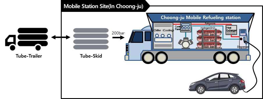
본 연구의 실증대상인 이동식수소스테이션은 Fig. 2와 같이 구축될 예정이다. 저장설비는 튜브트레일러를 통해 실증사이트에 공급되고, 이동식 수소스테이션 내에 압축기, 저장용기, 디스펜서가 탑재되어 구성되어 있다(Table 1 설비 사양 참조). 충전프로세스는 저장설비로부터 약 20 MPa의 수소를 공급받아 압축설비를 통해 약 82 MPa로 승압하여 압축가스설비로 저장되고, 자압(차압)을 통해 약 70 MPa의 압력으로 수소전기차(FCEV)를 충전한다.
3. 위험성평가를 위한 기초데이터 분석
3.1 가상사고 시나리오 구성
정량적 위험성평가(QRA)를 수행하기 위해 발생 가능한 가상사고 시나리오 구성이 필요하며, 이를 위해 기존 수소충전소의 발생한 사고를 분석하고 이동식수소스테이션의 공정상 위험요소를 정성적 위험성평가(Hazard and Operability Study)를 통해 가상사고 시나리오를 구성하였다. 튜브트레일러와 배관연결부 및 그 외 설비 연결의 체결 불량, 튜브트레일러 오발진에 의한 체결부 파손, 압축기 밸브 고장으로 인한 압축기 파손, 수소가스 배출 작업 중 미상의 점화원에 의한 화재, 차량 이동에 따른 진동발생으로 인해 피팅의 체결 불량으로 인한 가상사고 시나리오 5종을 구성하고 Table 2에 나타내었다.
3.2 사고시나리오의 사고발생 데이터
충전소 사고는 대부분 가스누출로 인한 사고이며,누출원의 크기별로 소규모 누출, 중규모 누출, 대규모 누출 3단계로 구성하여 Table 3에 제시하였다6). 국내에서는 이러한 누출사고에 대한 데이터베이스를 수집 중에 있어, 위험성평가 시 해외의 누출 데이터베이스를 활용하였다. 수소충전소 누출사고 데이터는 미국의 국립 연구소인 Sandia National Laboratory에서 제시한 사고빈도 데이터를 사용하였고7), 튜브트레일러 및 수소저장용기(high bank, medium bank)의 심각한 파열로 인한 사고를 사고 시나리오에 포함하여 위험성평가를 수행하였다8).
이동식수소스테이션 누출사고 발생 시, 사고예방설비로 수소가스검지기가 설치되어 가스를 차단하며, 유럽의 JRC 연구소에서 수소가스 검지기에 대해 응답시간을 측정한 실험데이터를 참고하여 최악의 조건으로 응답시간이 가장 길게 측정된 15초를 누출지속시간으로 선정하였다9).
3.3 충전소 부지 환경조건 분석
기상조건은 KOSHA GUIDE P-107-2016 (최악 및 대안의 누출 시나리오 선정에 관한 기술지침)에서 제시한 대기온도 및 기상조건 등의 조건을 최악의 시나리오로 선정하여 위험성평가를 수행하였다. 충전소 설치부지인 충청북도 충주의 봄, 여름, 가을, 겨울 4계절의 기상통계 데이터(풍속, 대기안정도, 기온)를 분석하여 지난 3년간의 최대온도를 worst case (여름조건)로 선정하고, 추가로 겨울 조건을 고려하여 Table 4에 제시하였다.
위험성평가를 위한 인구조건을 제시하기 위해 충전소 부지 인근 시설을 분석하였다. 인구분포는 주유소, 산업시설, 교회, 2021년 입주 예정인 오피스텔에 상주하는 일반인(public) 및 작업자(operator) 인원수를 조사하고 대략적인 근사값을 Table 5에 제시하였다.
점화원 조건은 충전소 부지 주변 환경을 고려하여, 인근도로에 주행하는 차량 및 인접해 있는 산업시설, 주유소를 주요 점화원으로 선정하여 Table 6에 제시하였다.
4. 정량적 위험성평가(QRA) 결과
이동식수소스테이션에 대한 위험성평가는 핵심설비에 대해 위험요인을 파악하고, 발생가능성(빈도)와 강도를 결정하여 예방대책을 수립하여 실행하는 과정으로, 위험도(risk)는 사고에 의한 피해영향(consequency)과 발생빈도(frequency)의 곱으로 정의한다10). 이러한 위험도에 대한 허용기준으로는 일반적으로 폭넓게 인정받고 있는 영국의 HSE에서 제안한 기준을 통해 이동식수소스테이션의 위험도를 분석하였고, 허용불가, 조건부허용, 허용가능한 조건으로 구분하여 위험도를 제시하여 Table 7에 나타내었다.
4.1 이동식수소스테이션 위험기여도(risk contribution)
Table 8은 이동식수소스테이션 핵심설비의 가상사고 시나리오 별 위험도 및 위험기여도(전체 사고시나리오에서 각각의 사고시나리오가 차지하는 위험비율)를 도출했다. 튜브트레일러의 대규모 누출 시, 사고빈도 1.8E-04/year, 치명도 1.07E-01로 위험도(사고빈도×치명도)는 1.92E-05로 가장 높은 위험도를 나타냈으며, 위험기여도는 23.4%로 가장 높게 분석된다. 또한 압축가스설비(high bank, middle bank)의 대규모 및 중규모 누출 발생 시 위험기여도가 높게 산출되었다. 튜브트레일러의 심각한 파열(catastrophic rupture)의 경우, 사고발생 시 치명도(average fatality)는 1.0으로 가장 높게 나타났으나, 사고빈도가 낮아 위험기여도가 낮게 나타났다. 이러한 가상사고 시나리오 별 위험도 순위는 이동식수소스테이션의 위험성을 분석하고 안전성을 확보하기 위한 데이터로 활용될 것이다.
4.2 개인적 위험성평가
개인적 위험도는 사고빈도와 피해영향을 고려한 결과로 위험의 근원 주위에 있는 사람에게 노출된 위험도이다. 이러한 위험성에 대해 본 과제의 부지에 있는 이동식수소스테이션의 총 위험도(total risk)는 8.16E-05이며, 작업자(operator)에 대한 위험도는 2.07E-06, 일반대중(public)에 대한 위험도는 6.09E-06으로 나타났다(Table 9). 산출된 위험도는 영국 HSE에서 제시한 작업자(workforce) 및 일반대중(public)에 대한 위험성기준을 만족(ALARP zone)하고 있는 것으로 분석된다.
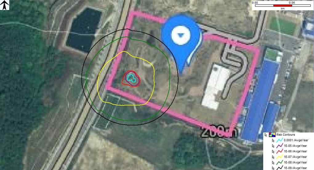
Fig. 3은 본 연구의 실증대상인 이동식 수소충전소의 ISO CONTOUR로 개인적 위험도 범위를 도식화 하였다. 개인적 위험도 시뮬레이션 결과 HSE에서 제안하고 있는 허용 불가 수준(unacceptable/intolerable)의 위험지역은 나타나지 않았으며, 작업현장 및 일반인에 대한 개인적 위험도는 모두 이동식수소충전소 실증사이트 허용범위 내에 분포하고 있는 것으로 분석된다.
4.3 사회적 위험성평가
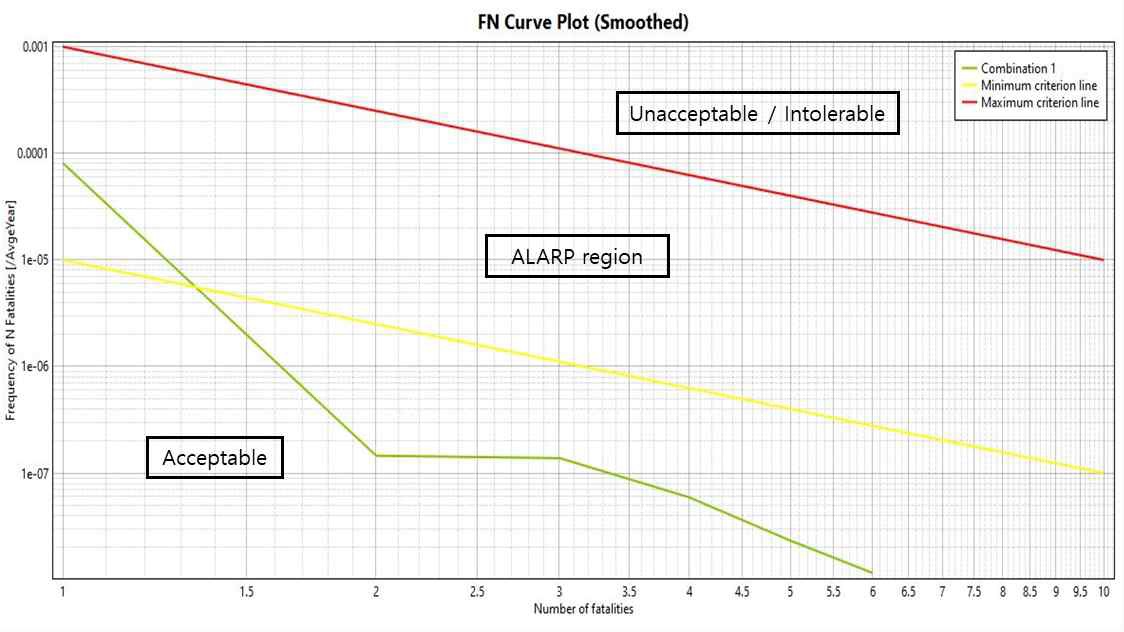
사회적 위험성(societal risk)은 한 집단의 사람들이 동시에 사고의 영향에 노출되는 위험도로, 예상되는 사고빈도(frequency of N fatalities)와 사고결과에 따른 예상 사망자 수(number of fatalities) 사이의 관계로 F-N frequency-number of fatality) 곡선을 사용하여, 허용불가 구간(unacceptable), 조건부 허용구간(ALARP zone), 무조건 허용구간(acceptable)으로 구분된다. 사회적 위험도는 Fig. 4와 같이 F/N 곡선이 도출 되었고, 대부분 무조건 허용구간으로 일부 구간에서 조건부 허용구간에 분포되는 것으로 분석되어 본 연구대상인 이동식수소스테이션은 허용가능한 수준에서 구축될 것으로 판단된다.
5. 결 론
본 연구는 2021년 충청북도 충주에 구축 예정인 이동식수소스테이션에 대한 정량적 위험성평가를 수행하였다. 기존에 구축되어 오던 고정식수소충전소와 다르게, 수소충전소가 허가받은 장소 간 이동하며 수소전기차를 충전하기 때문에 발생할 수 있는 진동에 의한 설비 피팅의 체결불량 등의 가상사고 시나리오를 도출하였다. 또한 도출된 사나리오에 대한 발생빈도와 충전소 주변 환경 등의 고려하여 개인적, 사회적 위험도를 도출하였다. 위험성평가 결과 개인적 위험도 및 사회적 위험도 대부분 구간에서 허용가능 범위에 해당하고 일부 조건부 허용(ALARP)구간 범위에 해당해 본 연구 대상인 이동식수소충전소는 허용가능한 수준에서 안전하게 구축 될 것으로 판단된다.
또한 이동식수소스테이션의 가상시나리오별 위험도를 산출하고 위험기여도를 분석하였다. 튜브트레일러 및 압축가스설비(high bank, medium bank)의 대규모 누출, 중규모 누출 시 위험기여도가 전체 기여도중 67.21%를 차지하고 있다. 이에 따라 가스누출검지경보장치, 긴급차단장치, 안전밸브 등의 안전장치의 주기적 관리를 통해 누출에 대한 대비가 필요할 것으로 판단된다. 또한 충전소가 이동 할 때마다, 진동으로 인한 충전소 핵심설비의 체결 불량, 파손, 고장 여부 등을 주기적으로 점검하여 안전관리를 한다면 안전하게 운용될 것으로 사료된다.
Acknowledgments
본 연구는 산업통상자원부(MOTIE) 및 한국에너지기술평가원(KETEP)의 2020년 산업기술혁신사업 지원으로 수행되었습니다(No. 20192910100160, 이동식 수소충전소 성능평가 및 안전관리 기술개발).
References
- Korea Government, “Comprehensive plan of Korean version new deal”, 2020. Retrieved from https://www.etrans.or.kr/download/newdeal.pdf, .
- Korea Ministry of Trade, Industry and Energy, “Hydrogeneconomy road map”, 2019. Retrieved from http://www.motie.go.kr/motie/ne/presse/press2/bbs/bbsView.do?bbs_cd_n=81&bbs_seq_n=161262, .
- Korea Ministry of Trade, Industry and Energy, “Special case standard for complex, packaged and mobile hydrogen refueling stations”, 2018. Retrieved from https://c11.kr/kl36, .
-
P. Kim, S. Kim, M. Yoo, and Y. Huh, “A study on safety analysis of stationary LPG - mobile hydrogen complex refueling stationn”, Journal of Energy Engineering, Vol. 28, No. 4, 2019, pp. 48-60.
[https://doi.org/10.5855/ENERGY.2019.28.4.048]

-
S. Kang, Y. Huh, and J. Moon, “A study on safety improvement for packaged hydrogen refueling station by risk assessment”, Trans Korean Hydrogen New Energy Soc, Vol. 28, No. 6, 2017, pp. 635-641.
[https://doi.org/10.7316/KHNES.2017.28.6.635]

-
H. Kim and S. Kang, “Analysis of damage range and impact of on-site hydrogen fueling station using quantitative risk assessment program (Hy-KoRAM)”, Trans Korean Hydrogen New Energy Soc, Vol. 31, No. 5, 2020, pp. 459-466.
[https://doi.org/10.7316/KHNES.2020.31.5.459]

-
J. LaChance, W. Houf, B. Middleton, and L. Fluer, “Analyses to support development of risk-informed separation distances for hydrogen codes and standards”, SANDIA REPORT, SAND2009-0874, 2009. Retrieved from https://energy.sandia.gov/wp-content/uploads/2018/05/SAND2009-0874-Analyses-to-Support-Development-of-Risk-Informed-Separation-Distances-for-Hydrogen-Codes-and-Standards.pdf, .
[https://doi.org/10.2172/983689]

- C. Nussey, “Failure frequencies for major failures of high pressure storage vessels at COMAH sites: a comparison of data used by HSE and the Netherlands”, HSE, 2006, pp. 25-31. Retrieved from https://www.hse.gov.uk/landuseplanning/c-nussey.pdf, .
- T. Hübert, J. Majewski, U. Banach, M. Detjens, and C. Tiebe, “Response time measurement of hydrogen sensors”, International Conference on Hydrogen Safety, 2017, pp. 4-6. Retrieved from https://h2tools.org/sites/default/files/2019-09/211.pdf, .
-
S. K. Kang and Y. S. Huh, “A study on the quantitative risk assessment of hydrogen-CNG complex refueling station”, Journal of the Korean Institute of Gas, Vol. 24, No. 1, 2020, pp 41-48.
[https://doi.org/10.7842/kigas.2020.24.1.41]

- KGS GC 101, “Classification code for explosive hazardous area on gas facility”, Korea Gas Safety Corporation, 2018. Retrieved from https://cyber.kgs.or.kr/kgscode.codeSearch.view.ex.do?onEngYn=F&pubFldCd=&pubMid=&pubCd=GC101_180712&stDayY=2008&stDayM=01&etDayY=2020&etDayM=12, .


